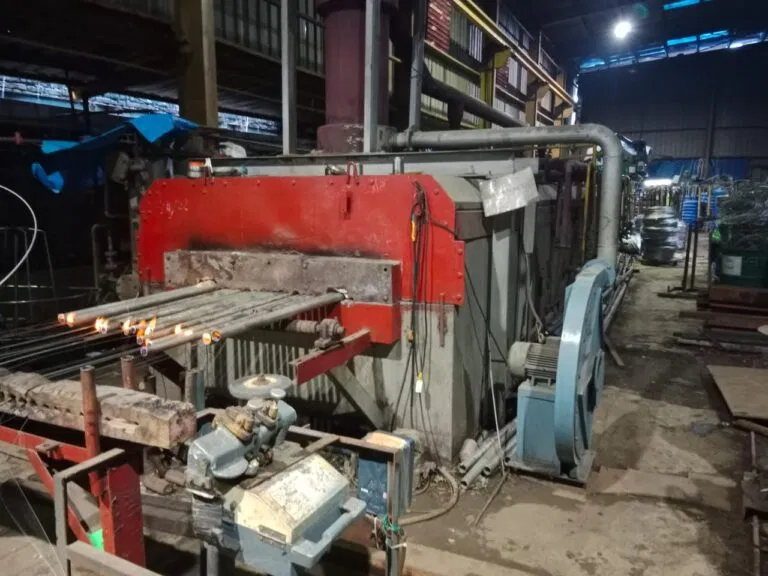
In 2026, furnace performance is no longer judged only by maximum temperature, production rate, or fuel consumption. Measurement integrity, refractory condition, and energy-transition readiness now determine yield, compliance, and lifecycle profitability. A temperature sensor that has drifted by 8°C can create the same commercial consequences as a damaged burner: inconsistent metallurgy, excessive scale, premature lining failure, and unplanned downtime. For every steel rolling mill, wire and cable industry plant, foundry, galvanizing line, and recycling operation, precision measurement is the foundation on which maintenance and quality decisions must be built.
Continental Furnaces approaches this challenge as an enduring engineering partnership. The objective is not simply to install thermal processing equipment; it is to create an industrial furnace system that remains measurable, maintainable, efficient, and adaptable throughout its operating life.
1. Precision Thermal Measurement Is the Foundation of Furnace Reliability
Why temperature data must be trusted
Furnace control systems are only as reliable as the signals entering them. A modern PLC may execute a control loop in milliseconds, but a degraded thermocouple, poorly positioned pyrometer, blocked oxygen probe, or unstable pressure transmitter can cause the system to make the wrong decision continuously.
The consequences include:
- Overheating and scale formation in billet reheating.
- Incomplete soaking in heat treatment furnaces.
- Excessive oxidation in a melting furnace for steel.
- Poor zinc-bath stability in a hot dip galvanizing plant.
- Uneven annealing in wire and cable industry production.
- Increased refractory heat load and accelerated lining degradation.
- Non-conformance during customer, ISO, or aerospace audits.
The correct approach is to treat instrumentation as a maintenance asset rather than an electrical accessory. Each measurement point requires a defined purpose, calibration history, installation standard, and failure-response procedure.
Pyrometry and AMS2750H readiness
SAE AMS2750H, revised in July 2024, defines pyrometric requirements for thermal processing equipment used for metallic materials. Its scope includes:
- Temperature sensors.
- Instrumentation.
- Correction factors and instrument offsets.
- System Accuracy Tests, or SAT.
- Temperature Uniformity Surveys, or TUS.
The official SAE AMS2750H specification remains the governing reference for aerospace and other controlled applications. Secondary summaries should support implementation, but they should never replace the standard itself.
For a production furnace, the practical measurement discipline includes:
- Calibrated control, recording, load, SAT, and TUS sensors.
- Traceable calibration certificates.
- Defined furnace class and instrumentation type.
- Documented correction factors.
- Scheduled SAT and TUS activity.
- Retention of survey records and corrective actions.
- Verification after sensor replacement, control-system modification, or refractory repair.
A furnace cannot demonstrate process control if it cannot demonstrate measurement control.

Type N versus Type K thermocouples
Both Type K and Type N thermocouples are widely used base-metal sensors and may be specified for applications governed by AMS2750H when the complete sensor, calibration, and installation meet the applicable requirements.
| Measurement consideration | Type K | Type N |
|---|---|---|
| Composition | Chromel–Alumel | Nicrosil–Nisil |
| Typical industrial use | General-purpose control, monitoring, SAT, and TUS | High-temperature control, recording, and long-duration service |
| Practical temperature capability | Commonly used up to approximately 1,100–1,200°C, depending on construction and environment | Similar high-temperature service range, subject to sensor design and instrument limitations |
| Drift behavior | More susceptible to high-temperature cycling effects and short-range ordering | Generally improved stability and lower drift in comparable high-temperature service |
| Availability | Very broad global availability | Broad and increasing availability for demanding applications |
| Selection priority | Economical, familiar, suitable for many applications | Preferred where long-term stability and repeatability are critical |
Type N is not automatically superior in every installation. The correct selection depends on process temperature, atmosphere, sheath construction, immersion conditions, replacement policy, and required traceability. However, Type N is often the stronger choice for critical control and over-temperature protection in high-temperature, heavily cycled furnaces.
Type K remains valuable for:
- Short-duration TUS probes.
- Lower-temperature monitoring.
- Redundant measurement.
- Applications with frequent planned sensor replacement.
- Situations where existing calibration infrastructure is built around Type K.
SAT and TUS are operating disciplines, not paperwork
A System Accuracy Test compares the installed measurement system with an independent calibrated standard. It verifies the combined performance of the sensor, wiring, transmitter, input card, and display or recorder.
A Temperature Uniformity Survey measures the temperature distribution throughout the qualified working zone. A control thermocouple may indicate 1,180°C while an unmeasured corner of the furnace is significantly colder or hotter. TUS detects that spatial variation.
Typical implementation considerations include:
- Higher-accuracy furnace classes require tighter control of sensor and instrument performance.
- SAT and TUS frequency depends on furnace class, instrumentation type, process requirements, and the governing specification.
- TUS thermocouples require controlled usage, calibration, identification, and disposition.
- A failed SAT or TUS requires documented investigation, not simply a sensor reset.
For a steel rolling mill, this protects billet temperature before rolling. For heat treatment furnaces, it protects the material property window. For an aluminum melting furnace, it supports repeatable melt quality and reduces unnecessary superheat.
2. Oxygen, Pressure, and Infrared Data Complete the Thermal Picture
Oxygen probing and furnace atmosphere
Temperature alone does not describe the furnace environment. Oxygen concentration, combustion excess air, dew point, and atmosphere potential can materially affect oxidation, decarburization, scale growth, and surface quality.
An oxygen probe strategy should define:
- Probe location and protection from direct flame impingement.
- Calibration and reference-air requirements.
- Cleaning and replacement intervals.
- Response to probe drift or signal instability.
- Relationship between oxygen readings, fuel flow, and combustion-air flow.
- Alarm limits for process protection.
In hydrogen-ready combustion, the measurement challenge becomes more demanding. Hydrogen changes flame speed, water-vapor concentration, heat-transfer behavior, and potentially NOx formation. The HyInHeat EU project is redesigning hydrogen combustion equipment, infrastructure, instrumentation, and control for steel and aluminum applications. Its work includes online process control and NOx monitoring, demonstrating that fuel conversion must be accompanied by an instrumentation redesign.
Furnace pressure monitoring
Small pressure deviations can create large quality and safety problems. Excessive negative pressure may draw uncontrolled air through door gaps, expansion joints, or damaged seals. Excessive positive pressure can force hot gases into the working area and increase heat loss.
A robust pressure-monitoring arrangement should include:
- Differential-pressure transmitters suitable for the furnace environment.
- Impulse-line protection and routine inspection.
- Alarm limits tied to operating zones.
- Trend recording rather than relying only on instantaneous displays.
- Interlocks where pressure instability can compromise combustion safety.
- Correlation with stack temperature, oxygen level, and fuel-air ratio.
Pressure trends often reveal seal degradation before a visual inspection does.
Thermal imaging and shell-temperature trending
Infrared scanning is one of the fastest ways to identify developing refractory and insulation problems without stopping production. It is particularly valuable for continuous furnaces, billet reheating lines, melting furnaces, and large batch heat treatment equipment.
A practical IR program should establish:
- A baseline scan after commissioning or a confirmed healthy reline.
- Repeat scans under comparable load and operating conditions.
- Fixed inspection routes and camera emissivity settings.
- Recorded ambient conditions and furnace setpoints.
- Trend points for doors, burner blocks, roof sections, hearth zones, expansion joints, and shell plates.
- Escalation criteria for persistent or rapidly increasing hot spots.
A 20–30°C increase above a stable local baseline can be used as an internal engineering alert for investigation, but it is not a universal pass/fail limit. The correct threshold depends on shell material, insulation design, ambient temperature, measurement uncertainty, and historical performance.
IR data becomes much more powerful when combined with:
- TUS results.
- Burner performance.
- Furnace pressure.
- Energy consumption per tonne.
- Refractory inspection records.
- Door and seal condition.
- Product quality and scale data.

3. Refractory Reliability Requires a Planned Maintenance Strategy
Why refractory failures are rarely sudden
A refractory failure may appear sudden to production personnel, but the degradation usually develops over time through:
- Thermal cycling.
- Mechanical impact from charge movement.
- Chemical attack from slag, flux, zinc, or process vapors.
- Flame impingement.
- Moisture ingress.
- Incorrect dry-out or heat-up procedures.
- Excessive local temperature.
- Structural movement and expansion-joint damage.
The most effective strategy is condition-based maintenance supported by routine inspection. This shifts the decision from “reline when failure occurs” to “reline the right zone during the right planned outage.”
A practical refractory inspection cycle
Every shift or daily
- Check shell-temperature indicators.
- Observe flame shape and burner stability.
- Inspect doors, seals, and visible joints.
- Record abnormal noise, smoke, or hot-gas leakage.
- Review pressure, oxygen, and fuel-air trends.
Weekly or monthly
- Complete targeted IR scans.
- Compare hot-spot locations with previous scans.
- Inspect burner blocks, hearth supports, skid systems, and charging areas.
- Review energy intensity per tonne.
- Verify that temperature sensors are not exposed to abnormal local heat.
During planned shutdowns
- Inspect lining thickness and surface erosion.
- Check cracks, spalling, joint opening, and anchor exposure.
- Inspect hearth flatness and charge-support condition.
- Validate door alignment and sealing.
- Confirm expansion allowances.
- Update the remaining-life assessment by zone.
Planned reline strategy
A reliable reline plan divides the furnace into criticality zones:
-
Zone A: Process-critical and high-temperature areas
Burner quarls, hearth hot spots, roof sections, melt-contact areas, and zones affecting product quality. -
Zone B: Reliability-critical areas
Doors, expansion joints, charging zones, discharge zones, and areas exposed to mechanical impact. -
Zone C: Secondary insulation and external areas
Sections where heat loss is measurable but immediate process risk is lower.
This classification supports a phased repair model:
- Patch repair for localized, stable damage.
- Partial reline during scheduled maintenance.
- Full reline when structural integrity, insulation performance, or process uniformity is compromised.
A thermal survey should be completed after every major refractory intervention. The objective is to confirm that the repair restored both thermal efficiency and temperature uniformity, not merely visual appearance.
4. Furnace Spare Parts Inventory Is a Production-Control Function
Unplanned downtime often extends because the correct component is unavailable, not because the repair is technically difficult. A critical spares program should classify parts by failure consequence, lead time, interchangeability, and storage requirements.
The essential inventory may include:
- Type N and Type K thermocouples.
- Ceramic protection tubes and thermowells.
- Oxygen-probe consumables and reference-air components.
- Pressure transmitters and impulse-line fittings.
- Burner nozzles, burner blocks, ignition electrodes, and flame scanners.
- Solenoid valves, regulators, filters, and flexible connectors.
- Heating elements, terminal assemblies, and contactors.
- PLC input modules, temperature controllers, relays, and fuses.
- Door seals, refractory shapes, castable repair materials, and anchors.
- Rollers, chains, bearings, lifting components, and limit switches.
The Continental Furnaces furnace spares and accessories gallery illustrates the importance of maintaining access to genuine, application-matched components.
For each critical part, record:
- OEM or approved-equivalent identification.
- Furnace location and quantity installed.
- Minimum and maximum stock levels.
- Typical lead time.
- Shelf-life requirements.
- Inspection and preservation requirements.
- Approved substitution rules.
- Responsible stores and maintenance personnel.
A planned spare costing 1% of an outage can prevent a production interruption costing 100 times more.

5. 2026 Energy Transition: Select the Pathway by Process Economics
Induction versus resistive and combustion heating
Electrification is not a single technology. Induction, resistive heating, hybrid gas-electric systems, and hydrogen combustion each solve different process problems.
A 2026 techno-economic study of steel billet reheating compared natural gas, hydrogen combustion, and induction heating. Its model reported indicative levelized costs of heat of:
- Approximately $31 per tonne for natural gas.
- Approximately $41 per tonne for induction.
- Approximately $76 per tonne for hydrogen combustion.
The same study identified approximate break-even conditions of $30/MWh electricity for induction and $1.75/kg hydrogen for parity with natural gas under its assumptions. These are not universal project quotations; energy prices, plant scale, grid connection, utilization, carbon costs, and capital expenditure will change the result.
| Decision factor | Traditional gas-fired furnace | 2026-ready induction or hybrid system |
|---|---|---|
| Heat delivery | Combustion and radiant/convective transfer | Direct electromagnetic or resistive energy input, often combined with combustion |
| Typical steel reheating temperature | Up to approximately 1,300°C | Application-dependent, with staged power and equalization |
| Indicative energy performance | Modern systems may reach approximately 60–75% thermal efficiency, depending on design and charging condition | Induction systems are commonly modeled at approximately 85% electrical-to-thermal efficiency |
| Scale formation | Often associated with 1–3% material loss, depending on atmosphere and residence time | Potentially lower because of shorter high-temperature exposure and absence of combustion gases |
| Main maintenance burden | Burners, flues, refractory, seals, fuel train | Coils, power electronics, cooling system, controls, refractory or insulation |
| Emissions profile | Direct CO₂ and combustion-related emissions | Depends on electricity source; direct combustion emissions can be reduced |
| Capital profile | Mature and comparatively lower initial investment | Higher electrical infrastructure and equipment investment |
| Best transition use | Existing high-throughput lines with optimized combustion | New lines, retrofit modules, peak-load trimming, or hybrid preheating |
The 2026 induction-versus-hydrogen reheating study also highlights an important engineering limitation: large steel sections can develop surface-to-core temperature gradients because steel is ferromagnetic below approximately 770°C. Frequency, power density, billet geometry, residence time, and equalization zones must therefore be designed together.
Hydrogen-ready combustion and hybrid gas-electric designs
Hydrogen is strategically important where direct electric heating cannot yet deliver the required heat flux, throughput, or retrofit practicality. The HyInHeat program is demonstrating that hydrogen adoption requires changes to:
- Burners and combustion chambers.
- Off-gas systems.
- Oxygen and NOx monitoring.
- Furnace control algorithms.
- Hydrogen storage and distribution infrastructure.
- Safety systems and operating procedures.
- Refractory selection and thermal mapping.
For a steel rolling mill, a hybrid design may combine:
- Existing gas-fired bulk heating.
- Hydrogen-capable burners.
- Induction preheating or final temperature trimming.
- Waste-heat recovery.
- Digital energy and quality monitoring.
This staged architecture reduces transition risk and creates a practical route from conventional operation to lower-carbon production.
6. A Phased Upgrade Roadmap for 2026 and Beyond
Phase 1: Assessment and planning : 0 to 3 months
- Map all temperature, oxygen, pressure, and energy measurements.
- Review calibration certificates, SAT/TUS records, and sensor failures.
- Establish shell-temperature and IR baselines.
- Audit refractory condition by furnace zone.
- Calculate energy consumption per tonne and material yield loss.
- Identify critical furnace spare parts and lead times.
- Define production, compliance, and decarbonization targets.
Phase 2: Measurement and reliability stabilization : 3 to 9 months
- Replace drifting or poorly specified sensors.
- Evaluate Type N for critical high-temperature control points.
- Upgrade pressure and oxygen trending.
- Introduce scheduled IR scanning.
- Correct door, seal, burner, and expansion-joint defects.
- Build minimum stock of critical spares.
- Standardize maintenance work instructions and escalation limits.
Phase 3: Digital control and condition-based maintenance : 6 to 18 months
- Integrate temperature, oxygen, pressure, fuel, power, and refractory data.
- Create dashboards for energy intensity, uniformity, and downtime.
- Use trend deviation to trigger inspection before failure.
- Link maintenance records with furnace zones and product quality.
- Add alarm rationalization and remote engineering support.
- Use historical data to optimize firing, soak time, and charging patterns.
Phase 4: Electrification and fuel-transition pilots : 12 to 36 months
- Conduct a site-specific induction-versus-resistive-versus-hydrogen study.
- Assess available electrical capacity and hydrogen infrastructure.
- Pilot induction trimming, preheating, or final equalization where appropriate.
- Validate hydrogen-compatible burners and refractory behavior.
- Repeat SAT, TUS, oxygen, pressure, and IR assessments after modification.
- Confirm the business case using CAPEX, OPEX, yield, carbon cost, and downtime risk.
For related Continental Furnaces capabilities, explore the thermal-processing furnace reference, recycling plant setup, and hot dip galvanizing plant gallery. These solutions sit within the wider portfolio of heat treatment furnaces, melting and recycling systems, galvanizing plants, pickling equipment, and industrial furnace systems.
Conclusion: Build Measurement Certainty Before Adding Furnace Capacity
The 2026 furnace upgrade is not defined by one burner, one sensor, or one fuel. It is defined by the integration of accurate measurement, reliable refractory, disciplined spare-parts planning, digital control, and commercially sound energy decisions.
Before investing in a new melting furnace for steel, aluminum melting furnace, billet reheating line, metal recycling furnace, or hot dip galvanizing plant, establish the condition of the existing process. Verify the data. Map the refractory. Quantify the losses. Then select the transition pathway that protects throughput and profitability.
Continental Furnaces brings more than 35 years of industrial furnace manufacturing and thermal-processing experience to this decision. Engage our engineers through the Continental Furnaces contact page to assess your furnace instrumentation, refractory reliability, spare-parts strategy, and 2026 electrification options.
Make precision and reliability the starting point for sustained competitive advantage.
Technical references
- SAE AMS2750H Pyrometry Specification
- HyInHeat EU Project: Hydrogen Technologies for Industrial Heating
- Techno-Economic Analysis of Induction and Hydrogen Reheating of Steel Billet
- Continental Furnaces Furnace Spares and Accessories
- Continental Furnaces Hot Dip Galvanizing Plant Gallery
- Continental Furnaces Recycling Plant Setup