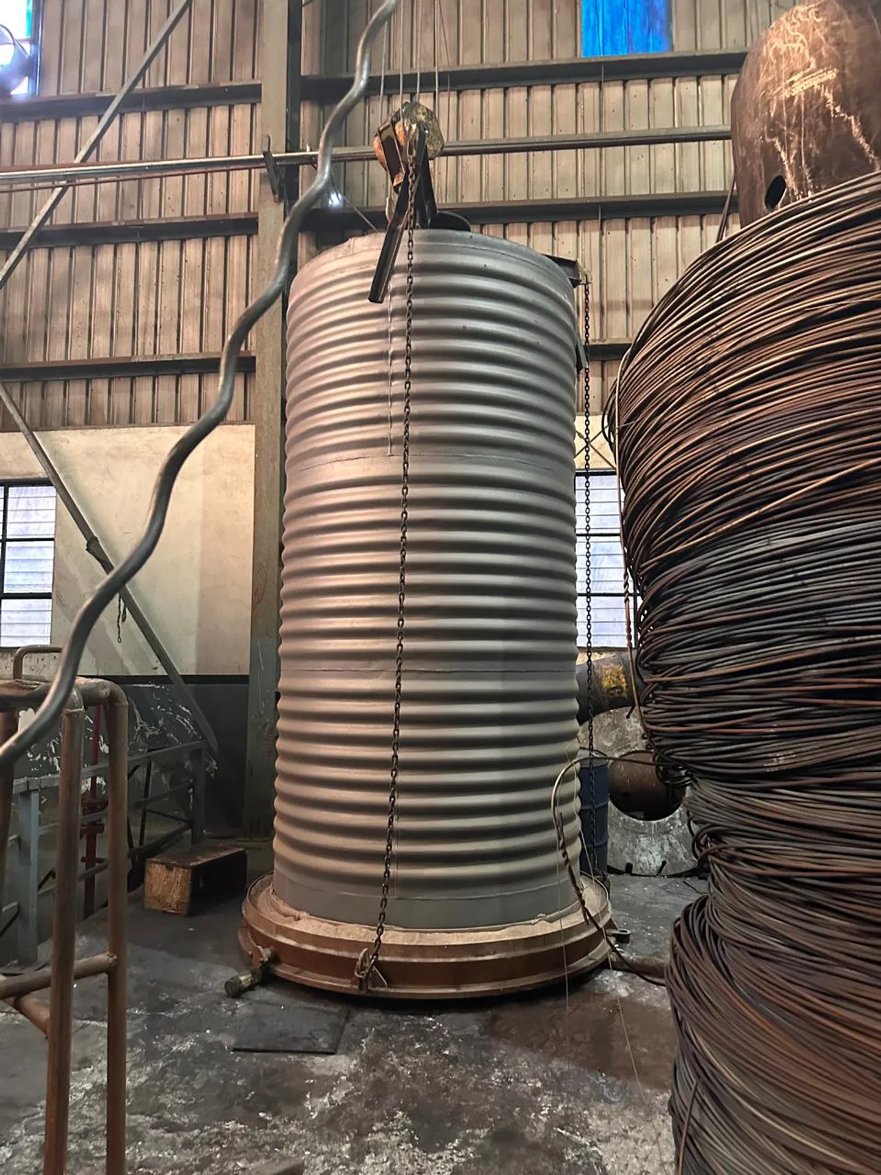
For wire and cable plants, annealing is not simply a heating step. It is a controlled way to restore ductility after drawing, achieve the required electrical and mechanical properties, and deliver a clean surface without disrupting production flow. In 2026, plant managers and procurement teams are weighing that quality requirement against energy costs, throughput, maintenance exposure and increasingly demanding sustainability targets.
The right choice of heat treatment furnaces starts with the wire material, product range, required properties and line layout, not a temperature rating alone. This guide outlines the main process options, benchmarks and practical decisions for copper and aluminium wire manufacturers.
Match the thermal cycle to the wire
Cold drawing increases strength and reduces ductility. Annealing restores softness and formability through controlled heating and cooling. The recipe depends on alloy, wire diameter, prior reduction, line speed and the final specification.
- Copper: A broad planning range for electrical wire annealing is approximately 450–650°C. This is a starting point for process development, not a universal recipe. A published continuous copper-wire study, for example, evaluated treatments above 500°C; production setpoints still need validation against the actual product and line.
- Aluminium: Temperature and time must be set for the specific alloy and temper. Do not apply a copper recipe or infer a working setpoint from a furnace’s maximum design temperature.
- Quality checks: Confirm tensile strength, elongation and electrical resistivity, and inspect for surface defects. Track results by product diameter and recipe.
A capable industrial furnace manufacturer will define the system around the complete production requirement: temperature uniformity, line speed, atmosphere, cooling, controls and the means to verify the finished wire. Continental Furnaces’ heat treatment furnaces are designed with customized process requirements in mind.
Bright annealing: atmosphere control is part of the process
Bright annealing heats wire in a controlled atmosphere to limit oxidation and preserve a clean surface. Nitrogen is commonly used as a carrier gas, with hydrogen added in some processes to support oxide reduction. Published equipment specifications illustrate the range of possible configurations: Tenova’s continuous wire furnace describes operation up to 1,050°C in process gas, while Italimpianti’s FRC/F system lists a 950°C maximum furnace temperature and a 75% hydrogen/25% nitrogen atmosphere. These are equipment limits and configuration examples, not recommended wire setpoints.
Atmosphere quality depends on the full system, including gas purity, sealing, leak prevention, purge strategy and monitoring. For a bright-annealing line, include exit-surface inspection and atmosphere data in the process record. Aluminium requires particular attention: its stable oxide film makes surface outcomes alloy- and process-specific.
Batch versus continuous annealing
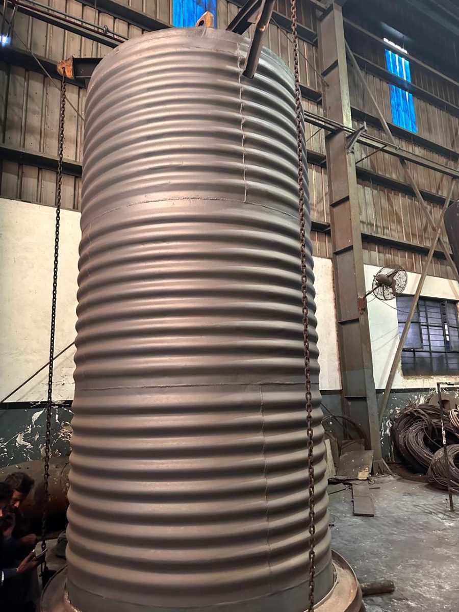
The choice between pot or bell-type batch treatment and continuous strand annealing is a production-system decision. It affects scheduling, work-in-process, labour, atmosphere use and how easily the process can keep pace with drawing.
| Consideration | Batch / bell annealing | Continuous / in-line annealing |
|---|---|---|
| Best fit | Multiple products, varied lots or flexible production schedules | High-volume, repeatable products and steady throughput |
| Process flow | Coils or loads are treated together; production waits for the cycle | Wire moves through defined heating, holding and cooling zones |
| Production planning | Batch loading and unloading require coordination | Can integrate with drawing or downstream handling |
| Recipe flexibility | Strong flexibility between batches | Efficient when the line runs stable, repeatable recipes |
| Quality focus | Uniformity through the load and repeatable batch recipes | Stable temperature, line speed and atmosphere along the strand |
| Key cost drivers | Load size, heat-up/cool-down time, utilisation and handling | Line utilisation, speed, atmosphere consumption and integration |
“In-line” can refer to resistance annealing directly after drawing, or to a continuous furnace stage. These arrangements are not interchangeable: compare the actual metallurgical outcome and total line performance. For a batch system, review Continental Furnaces’ bell-type annealing furnace gallery.

Measure energy per tonne with a clear boundary
A single, broadly accepted specific-energy figure for wire annealing is not available across different plant designs and product mixes. Electricity, fuel, atmosphere, line utilisation and whether upstream drawing is included all change the result. A useful plant KPI is:
Specific energy (kWh/t) = total annealing energy used ÷ tonnes of accepted annealed wire
Record electricity, fuel-equivalent energy, process gases and key auxiliaries separately. Report copper and aluminium products by diameter, line speed and furnace load. This prevents drawing energy or an under-loaded shift from distorting the annealer benchmark.
Improvements should be verified against a baseline. In one published radiant-tube burner project, combustion air was preheated to 590°C, the design targeted 48% waste-heat recovery, and reported fuel-gas use fell by 12% compared with the existing arrangement. Those are project-specific results, not guaranteed savings for every wire line. The JFE Steel technical report provides further detail.
Practical levers include:
- Recuperative or regenerative burners and exhaust heat recovery.
- Better insulation and reduced heat loss through doors, seals and furnace openings.
- Purge and gas-flow settings matched to validated process needs.
- Controls linking temperature and line speed to the approved recipe.
- Production planning that avoids extended operation at low utilisation.
2026 technology: hydrogen readiness and Industry 4.0
Hydrogen-ready burners and hydrogen-containing process atmospheres are receiving increased attention. But “hydrogen-ready” must be a verified system specification, not just a burner label. Assess the fuel train, materials, seals, leak detection, ventilation, purge logic, flame supervision, controls and applicable emissions requirements. A copper-industry demonstration reported a 40-tonne bell-annealing cycle using 100% hydrogen for heating; it demonstrates technical progress, not an automatic business case for every plant. Hydrogen can also change energy demand, so calculate operating cost and emissions using the plant’s actual supply and system boundary.
Industry 4.0 monitoring adds value when it connects process signals to product quality and maintenance action. Useful data include:
- Temperature by zone and line speed.
- Fuel and electrical consumption per accepted tonne.
- Gas composition, flow and relevant atmosphere measurements.
- Alarm history, downtime causes and maintenance events.
- Recipe, batch or coil traceability linked to quality results.
Other industrial furnace systems, from a steel rolling mill reheating line to a hot dip galvanizing plant, have different duties and design constraints. Likewise, an aluminum melting furnace, melting furnace for steel or metal recycling furnace should not be treated as an annealing-line specification. Define each system around its process.
Spare parts readiness and preventive maintenance
A planned maintenance programme protects product consistency as well as uptime. Review wear items and critical components against lead time, failure consequence and serviceability. A plant-specific furnace spare parts register may include burner components, thermocouples, control instruments, seals, fans, drive components and other items identified in the equipment documentation.
Prioritise:
- Routine checks of temperature sensors, burner performance, seals and insulation.
- Inspection of fans, drives, interlocks and gas-safety systems.
- Trend reviews of temperature deviation, utility use and unplanned stops.
- Stocking critical parts according to supplier lead times and downtime risk.
- Keeping approved drawings, component specifications and maintenance records accessible.
A phased roadmap for plant teams
Phase 1: Assessment and planning
Map wire grades, diameters, throughput, quality targets, production mix and existing line constraints. Establish a measured energy and downtime baseline.
Phase 2: Process and equipment selection
Compare batch and continuous options against required flexibility, capacity, atmosphere, footprint, utilities and integration needs. Specify control and quality-validation requirements alongside furnace design.
Phase 3: Commissioning and validation
Prove recipes against mechanical and electrical properties, surface requirements and stable line operation. Agree on acceptance criteria before ramp-up.
Phase 4: Lifecycle optimisation
Review energy per accepted tonne, maintenance trends, spare-parts readiness and quality performance at defined intervals. Apply upgrades only where measured results justify the investment.
Build the next step around your plant’s requirements
Continental Furnaces brings more than 35 years of experience in customized thermal processing solutions. The right outcome is not just a furnace delivery; it is a system selected for your wire, production plan and operating priorities, backed by a relationship focused on lifecycle support and minimal downtime.
Contact Continental Furnaces to discuss your annealing requirements, energy baseline, controls and spare-parts plan. An informed consultation is a practical first step toward sustained competitive advantage, and an enduring partnership in thermal processing.