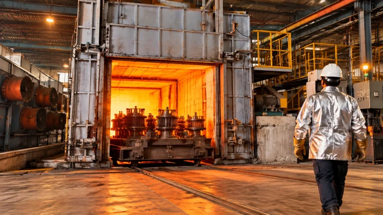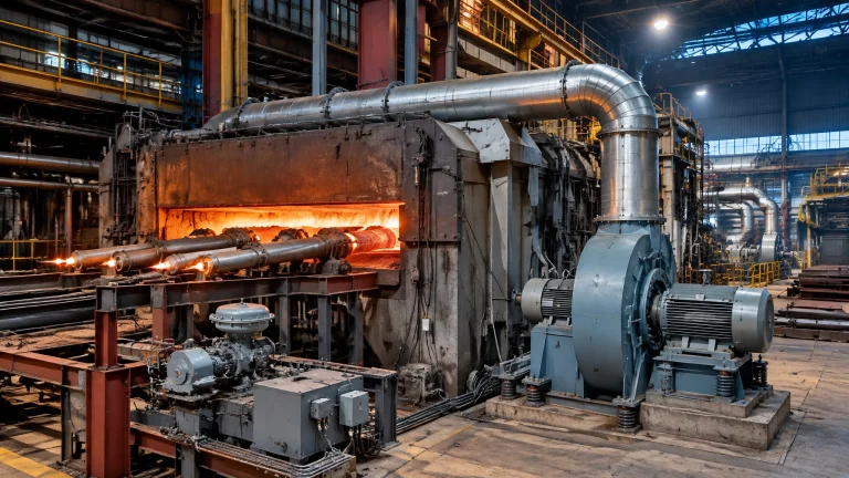
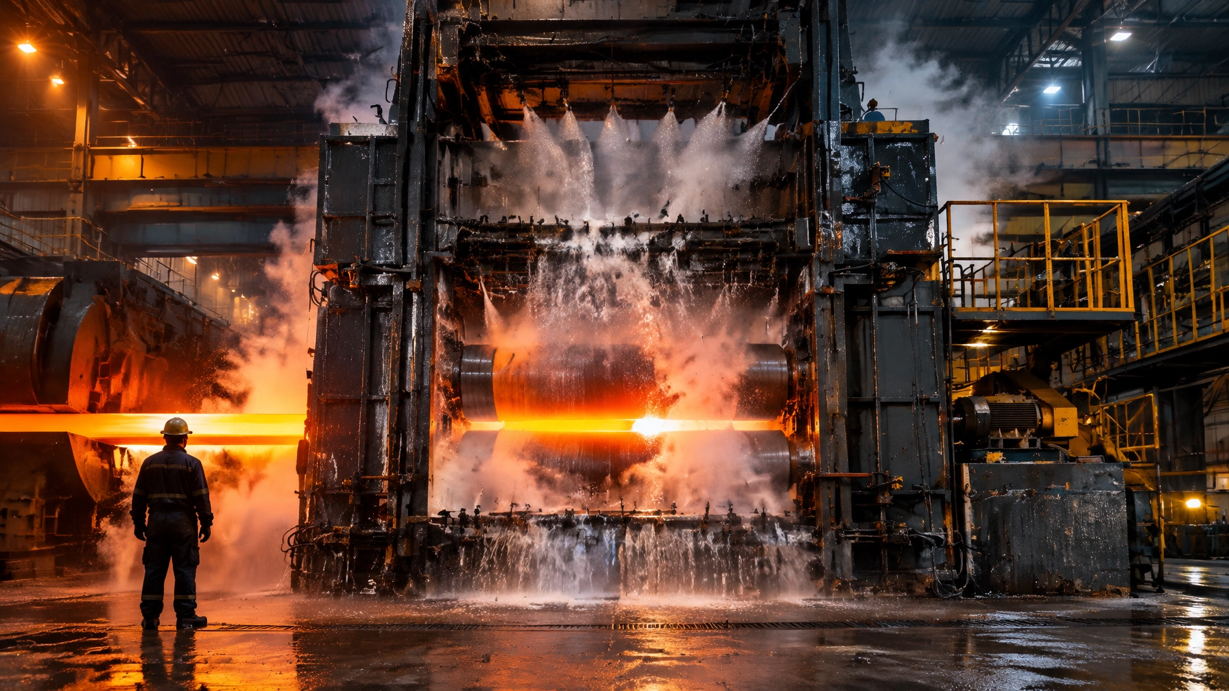
Work roll cooling is usually budgeted and maintained as a utility, then managed as a fixed recipe. That view misses its production role. Roll cooling is one of the mill’s fastest-acting profile and flatness actuators, and one of the cheapest controls to lose through wear, blockage or misalignment. The thermal crown it produces is a controllable dimension, not weather. Many mills detect drift indirectly through strip shape complaints and roll-shop consumption, months after the underlying spray condition changed. Spray-curtain condition, water quality and nozzle wear belong in the same reliability conversation as roll grade and bearing condition.
All figures are indicative benchmarks drawn from published conference papers, supplier technical literature, plant reports and peer-reviewed modelling studies, and vary with mill type, stand position, roll grade and diameter, strip width and grade, coolant type and concentration, water chemistry, nozzle family and instrumentation.
The thermal budget of a work roll: where the heat enters and how little of it leaves by design
Heat enters the work roll at the bite through conduction from the strip, friction and deformation work. Some heat is lost to air and wash-off coolant before the strip reaches the bite, but the roll receives a substantial, repeated thermal pulse. Any point on the roll surface heats in the bite and cools under the spray, once per revolution.
Saha et al. modelled the upper work roll of the No. 1 finishing stand at Tata Steel’s hot strip mill. For the roll bite, the study used a heat transfer coefficient of about 37.6 kW/(m² K) during the first 30 ms of contact and about 18 kW/(m² K) thereafter. At a total cooling flow near 317 m³/h, predicted surface peaks over the first six revolutions rose from about 490 to 521°C, while minima rose from about 51 to 80°C. The predicted roll body temperature was about 184.5°C. For a separate roughing-mill validation, predicted surface peaks of 545°C and 565°C compared with measured values of 500°C and 539°C. These are model and trial results, not universal operating setpoints. (Saha et al., ISIJ International, 2005)
The thermally active layer is thin. Using Tseng’s penetration-depth relation, Saha et al. calculated a depth of about 7.2 mm for the studied roll and selected a 12 mm layer for modelling. This is where much of the temperature swing and plastic strain per cycle occur.
The fatigue mechanism is direct. As the hot surface leaves the bite, it attempts to expand against the much cooler roll body. The constraint puts the surface into compression, where it can yield. Cooling reverses the stress into tension, where further yielding may occur. The resulting hysteresis loop repeats every revolution. Repeated cycles produce fire cracking and, in severe cases, spalling. A sound roll core does not prevent retirement for surface damage, and removing a spray row is not a neutral change.
Lechler’s design intent is to cool the surface as early as possible behind the gap, from roughly 600 to 800°C to below 300°C, while maintaining an average work roll temperature around 50 to 70°C. Effective cooling influences:
- Roll life and rolling campaign length
- Roll-change frequency and roll-shop grinding volume
- Strip surface quality and profile stability
- Risk of roll breakage from differential expansion
Thermal crown as a controllable dimension, not a seasonal surprise
A roll profile has a fixed portion established by grinding and a flexible portion established in operation by cooling: the thermal camber. Cooling is an actuator. Adjusting it to the strip width being rolled is normal practice, not an optional optimisation.
Top and bottom work rolls should receive symmetrical spray application so they react in a comparable way. Entry and exit side conditions can legitimately differ. Misaligned headers create different spray footprints on the drive and operator sides, which can produce roll profile deviation, strip steering trouble in tandem mills, and flatness or surface defects.
Selective cooling separates basic cooling from zonal correction. A typical arrangement assigns roughly 20 to 30 percent of header flow to basic rows aimed towards the roll gap, with 70 to 80 percent available to selective rows. Selective zones are aligned with the shape-measuring roll on the exit side, and top and bottom nozzles in the same zone operate together. For correction to take effect in time, Lechler advises coolant temperature at least 15°C below roll surface temperature. A cold-mill coolant that is too warm may therefore circulate without providing useful correction.
Saha et al. quantified how placement, flow and row count affect predicted strain:
- Moving the lowermost exit row from 130° near the back-up roll to 40° near the bite reduced predicted body temperature from 194°C to 181.5°C and plastic strain per cycle from 4.002 to 3.830 × 10⁻³. The plant’s earlier change from about 100° to 65° reduced body temperature from 189°C to 184.5°C and strain from 3.921 to 3.873 × 10⁻³. Moving a header a few degrees can deliver a real but modest return. Restoring degraded spray performance usually offers the larger gain.
- Raising total flow by 10 percent from the existing condition reduced predicted strain from 3.873 to 3.693 × 10⁻³. A further 10 percent produced almost no change, to 3.689 × 10⁻³. The study identified about 350 m³/h, 10 percent above the then-current 317 m³/h, as an optimum for the existing arrangement. This is a classic diminishing-returns curve, and a strong argument against trying to cure a distribution fault simply by opening a valve.
- Withdrawing the uppermost exit row, reducing total water by about 18 percent, raised predicted roll body temperature to 206°C and strain to 4.506 × 10⁻³. Adding a fourth exit row with 20 percent more water reduced strain to 3.466 × 10⁻³, about 10.5 percent below the existing condition.
Row count and flow are separate levers. Rows nearer the bite are worth more than rows near the back-up roll because they remove heat before it conducts further into the roll.

Spray-curtain engineering: the geometry decides what the pump can deliver
At rolling speed, any point on the roll spends very little time under a spray. The covered arc, not the nominal flow rate, sets how much heat can leave during that brief contact. Maximise useful surface coverage first, then tune the flow.
Full-cone nozzles produce a relatively uniform, broad footprint and can transfer more heat per litre because the roll remains under the larger footprint for longer. But adjacent cones can clash and create a ridge of coolant. Flat jets produce larger droplets with higher impact, helping them penetrate the water film on the roll, and their simpler internal geometry needs no vane insert. In most roll-cooling applications, flat jets arranged with parabolic distribution and non-interfering footprints are preferred. Self-aligning fixings exist for a practical reason: alignment is one of the details that fails in service.
Lechler experiments found cooling effect peaking at an offset angle near 60° to the horizontal. Increasing the angle to 75° raised spray height and reduced impact at the outer footprint areas. Nozzles should also be directed perpendicular to the roll axis, giving symmetrical footprints and a high heat-transfer coefficient. Asymmetric footprints mean uneven cooling and lubrication.
Tucker defines overlap as pattern width divided by nozzle pitch. Keep overlap around 10 to 30 percent, never above 50 percent, and do not allow under-spraying. Gaps produce stripes on the strip. Excessive overlap also destroys zonal sensitivity: a zone heavily overlapping its neighbours cannot be switched to correct a local pocket of thermal expansion. Tucker documented a hot-mill edge-temperature problem caused by 100 mm nozzle spacing, a flat pattern and large overlaps. Moving to 75 mm spacing and a more vertical spray restored zonal sensitivity.
Typical zonal spacing reported by Tucker:
- Hot aluminium: 75 mm, with 2 to 3 rows
- Cold aluminium: 52 mm, edge controls at 25 to 26 mm, with 2 to 3 rows
- Cold steel: 52 mm, with 1 or 2 rows
- Cold copper and brass: 52 or 26 mm, with 2 rows
- Hot steel mill: 75 or 52 mm, with 2 or 3 rows
Nozzle flow varies with the square root of pressure. A header running low on pressure may present as a cooling fault, while the underlying issue is poor distribution. Oversized distribution lines, abrupt direction changes, internal burrs and poor welds create turbulence that can erode headers from within. Erosion corrosion becomes a particular concern above roughly 5 m/s coolant velocity.
The cheapest convincing spray audits remain the grease test and the laminated-paper method. Coat the roll, fire the sprays briefly, then read the footprints on the barrel after withdrawal; alternatively, use laminated paper to capture the pattern. A photograph of a distorted footprint can settle an argument that flow meters cannot.
Roll cooling levers and their indicative effect on roll condition
| Lever | What changes physically | Indicative magnitude | Where the effect shows up | Source basis |
|---|---|---|---|---|
| Total cooling flow about 10 percent above a base condition | Greater spray flux over the existing arrangement | Predicted plastic strain per cycle falls from 3.873 to 3.693 × 10⁻³; negligible further gain at 20 percent | Thermal fatigue exposure and roll condition | Saha et al. |
| One additional exit-side nozzle row with about 20 percent more water | Adds an exit-side cooling row and raises total flow | Plastic strain per cycle 3.466 × 10⁻³, roughly 10.5 percent lower | Surface fatigue and expected roll life | Saha et al. |
| Withdrawing the uppermost exit row, about 18 percent less water | Removes a cooling row and reduces total flow | Roll body temperature rises from 184.5°C to about 206°C; strain reaches 4.506 × 10⁻³ | Higher body temperature and thermal fatigue | Saha et al. |
| Moving the lowermost exit row from 130° to 40° from the bite | Starts cooling closer to the bite | Roll body temperature falls from 194°C to 181.5°C | Earlier heat extraction and lower predicted strain | Saha et al. |
| Nozzle offset angle at about 60° rather than 75° | Improves useful impact across the footprint | Higher cooling effect for the same flow | Coverage and heat transfer | Lechler |
| Spray overlap held at 10 to 30 percent rather than several hundred percent | Restores distinct zonal footprints | Restored zonal sensitivity and faster shape response | Flatness and local profile correction | Tucker |
| Filtration to a maximum particle size of one third of the smallest nozzle passage | Limits solids capable of obstructing the nozzle | Reduced clogging and pattern distortion | Flow stability and footprint quality | Lechler |
| Replacing nozzles at measured over-capacity rather than on pattern appearance | Returns worn nozzle capacity towards design | Flow, pumping and water use back in line with design | Spray performance and utility consumption | Spraying Systems |
Caveat: This table is not a substitute for a mill-specific cooling study. The magnitudes come from a single-stand modelling study and supplier test work under stated assumptions.
Nozzle condition and the water you actually have
This section concerns what coolant does to the spray curtain. It does not cover mill water circuit design, scale-pit sizing or pump selection, which are separate engineering subjects.
Nozzle wear enlarges the orifice, raises flow, increases drop size, reduces impact and degrades the spray pattern. Flat fans can develop streaks, heavier centre flow and a narrower effective spray angle. The change is nearly invisible by eye: gradual erosion cannot be reliably judged by looking at a nozzle or its spray. That is the central maintenance problem.
Spraying Systems gives a general cost example: a 100 gpm system with nozzles operating 15 percent over rated capacity incurs about US$182,800 per year in water and chemical costs under its stated assumptions: water at US$2.75 per 1,000 gallons, chemical at US$1.00 per gallon at 10:1 dilution, and 2,080 operating hours. This is not a mill-specific cost estimate, but the arithmetic applies: over-capacity flow adds recurring cost before electricity, scrap or downtime.
Set a baseline immediately after installation. Record each nozzle’s flow rate, manifold pressure, drop size, pattern, alignment and application result, then recheck those same items on a schedule. Without that record, wear can only be suspected, not demonstrated.
A 2025 CSN hot strip mill study presented at ABM found water with Langelier Saturation Index values of about −3.04 to −3.21, low alkalinity and hardness, and inadequate pH, indicating a strongly corrosive environment. Total suspended solids peaked at 192 mg/L on one shift, indicating abrasion and clogging potential. X-ray fluorescence of nozzle residue identified Fe₂O₃, Al₂O₃, MnO, SiO₂ and ZnO, together with SO₃ and Cl at concentrations well above those in rolling-floor iron fines. The evidence pointed to both corrosion-product transport and corrosive attack. The study’s conclusion was to correct water chemistry and filtration to reduce nozzle wear. (CSN nozzle-wear study, ABM 2025)
The filtration rule is simple: maximum particle size should not exceed one third of the smallest internal nozzle passage. If it does, expect:
- Throttled flow and tilted jets
- Higher header pressure for the same apparent flow
- Missing zones and distorted footprints
- Flatness defects wrongly blamed on the shape-control model
A practical inspection routine includes:
- Check header alignment from drive side to operator side.
- Audit the footprint by grease test after each roll-change campaign.
- Compare nozzle flow with the commissioning sheet.
- Trend header pressure against flow.
- Record strainer differential pressure.
- Hold nozzles, retaining nuts and welding nipples at the correct offset angle. A mid-campaign replacement from the wrong spares box can silently change spray angle.

What an unstable spray curtain costs: rolls, campaigns and claims
Roll consumption is the most visible economic line. ArcelorMittal Tubarão’s hot strip mill six-sigma roll programme reported about R$16 million less in roll CAPEX, 32 additional production hours from improved roll campaigns and about R$18 million of capital avoided on a new grinding machine that would otherwise have been needed for higher annual production. The plant had increased output from 2.5 to 4.1 million tonnes per year after adding a second reheating furnace. These are plant-reported, currency- and context-specific outcomes, not a forecast for another mill. (ArcelorMittal Tubarão roll programme, ABM 2019)
At Tata Steel IJmuiden HSM2, a high-turbulence roll cooling trial with CRM Group reported that after implementation at the FM2 top work roll, the proportion of rolls with a poor roll surface fell by more than a factor of ten. This is a compelling quantified indication that cooling quality, rather than roll grade alone, can be the limiting factor. (IJmuiden HTRC trial, IRC 2019)
Indirect costs compound the roll bill:
- Roll-shop grinding hours and grinding-wheel consumption
- Spare roll inventory tied up to cover premature withdrawals
- In-campaign roll changes, each with yield and temperature losses
- Strip-shape claims, downgrading and avoidable quality disputes
- Process engineering hours spent retuning the shape model around a cooling fault
When flatness drifts, engineers naturally look first at bending, shifting and the control model. These are visible and adjustable. A partly blocked nozzle row or worn header is less visible and often unattended. The cheapest fix is frequently in the least-examined subsystem. The same logic applies to the cooling-water pumping load, a continuous electrical demand serving a low-grade thermal duty.

Roll cooling failure modes: what you see, what it usually is, first check
| Symptom | Likely cause | First check | Risk if left |
|---|---|---|---|
| Flatness deviation the shape model cannot hold, drifting across a campaign | Partial nozzle blockage or a zone running off design flow | Nozzle flow check against the commissioning sheet in the worst zone | Roll profile deviation and shape claims within days |
| Strip edge temperature or edge shape problems that no bending adjustment fixes | Overlap too high and zonal sensitivity lost, often after a nozzle substitution | Footprint audit and overlap calculation from the header drawing | Chronic edge defects and downstream processing problems |
| Roll body temperature above its historical level, fire cracking earlier than expected | Worn nozzles flowing over capacity, or a spray row blinded | Header flow against pressure, plus a footprint grease test | Campaign shortened and grinding volume up |
| One side of the roll barrel hotter than the other | Header misalignment, drive side against operator side | Mechanical alignment check and a photograph of the two footprints | Strip steering and differential force problems, particularly in tandem mills |
| Strip surface defects traced to roll surface, roll withdrawn early | Cooling starting too far from the roll gap, wet angle too large | Position of the first exit row relative to the bite | Rolling campaign cost and rolled-in defects |
| Recurring nozzle failures and erratic flows | Water quality: high suspended solids, corrosive chemistry, strainer bypass | LSI and suspended solids on the coolant, plus strainer differential pressure | Continuous replacement cost and unmeasured cooling variation |
Symptoms overlap heavily. This table is a triage order, not a diagnosis. A flow check and a footprint photograph will resolve most of these rows in a single stop.
2026 technology and market updates
Low-pressure, high-turbulence cooling displaces high-pressure spraying
The design philosophy is shifting from pressure as a proxy for cooling performance to geometry and controlled turbulence as ways to deliver impact. Tata Steel IJmuiden’s HTRC unit, developed with CRM Group, operates at up to about 700 m³/h per unit at only 2 to 3 bar. Mounted on the exit guide with a 5 to 15 mm gap to the roll, it sends water upwards in the direction of roll rotation and deliberately minimises the wet angle to limit repeated heat penetration.
The reported maintenance details matter as much as the flow figure. A wiper nose and blocks maintain the gap. Excessive force wears them; insufficient pressure allows water to push the unit away and leak onto the strip. The installation had to fit inside an eight-hour stop and remain fully reversible. The entry cooling was blinded to allow roll-bite lubrication.
Primetals’ Power Work Roll Cooling takes a related approach: 3 bar at the nozzle, solid-jet nozzles for impingement, and a three-chamber header for dynamic water-crown control. The supplier claims up to 70 percent energy saving in water supply at essentially the same flow. The common thread is clear: pressure had been spent to buy impact that better geometry could deliver more efficiently.
Profile actuators converge on one control layer
The fourth-generation Pair-Cross Mill, published in November 2026, was installed at Nucor Decatur: F2 from March 2022, followed by F1 and F3 over the next eighteen months. Sensor-equipped cross cylinders provide automatic roll-position correction and liner-wear compensation. Reported outcomes included improvements in differential force ratio and roll levelling, with differential force approaching zero at zero levelling, stable operation and fewer in-bar interventions. Average housing-liner wear was reported at only 0.4 to 0.6 mm over thirty months, compared with six-monthly surveying and adjustment on the first-generation mill.
On the control side, Primetals’ Contour and Flatness Optimizer uses an online material-flow model and can work across grinding types, Pair-Cross and bending. Dynamic Profile Control runs in basic automation with adaptive machine learning. As mechanical actuators become more precise, the thermal actuator must become equally repeatable. Otherwise, the model spends its authority compensating for a spray curtain that nobody is measuring.
Spray condition becomes a measured variable rather than an assumption
Supplier nozzle-wear services increasingly verify flow and pattern, supporting a move from reactive replacement to measured over-capacity. That work complements water-quality analysis such as the CSN study and reinforces the filtration rule. A nozzle 15 percent over capacity is not 15 percent better. Its drop size, impact and footprint have all moved away from the design point.
Roll cooling is being re-read as an energy and water asset
The opportunity is to reduce unnecessary flow and treatment load where modelling shows diminishing returns, and to blind complete rows where lubrication has taken over part of the duty. Any reduction must be justified by a cooling study, not by a utility budget. The Tata study’s diminishing-returns curve is the right instrument for that decision.
What this means across your furnace and mill fleet
The thermal-management principle extends across the production chain, from roll metallurgy to downstream surface quality:
- For a steel rolling mill, roll-heat-treatment, normalising and annealing furnaces affect the rolls whose thermal crown the mill later controls. A mill that manages roll cooling well can also specify furnace uniformity and cooling rates matched to roll grades.
- Roll performance depends on the heat treatment the roll received. Post-grinding stress relief and tempering discipline in heat treatment furnaces form part of the same reliability chain. In a steel rolling mill, coordination between roll-shop practice and cooling condition helps protect that investment.
- An aluminum melting furnace and a melting furnace for steel influence upstream melt quality and inclusion content, which can reach the roll as strip-surface defects. Continental Furnaces’ melting and recycling solutions address this upstream side.
- A metal recycling furnace processes scrap whose quality and residual elements can affect roll wear and surface defects.
- Furnace spare parts and spray headers, nozzles, retaining nuts and welding nipples are all consumables with lead times. Holding the correct offset-angle spares is the same sound discipline as holding furnace spares. See furnace spares and accessories.
- A hot dip galvanizing plant needs consistent strip shape and crown entering the line to support coating uniformity. Stable thermal crown also helps feed a pickling plant with better-controlled strip surface condition.
- In the wire and cable industry, wire rod cooled on a Stelmor-type conveyor inherits the same dependence on consistent thermal conditions across its section.
- For new industrial furnace systems and thermal processing equipment, buyers should require documented spray-header drawings, nozzle schedules, commissioning flow baselines and a cooling study, just as they require furnace documentation from an industrial furnace manufacturer.
A four-phase roadmap
Phase 1: Baseline and audit, 30 to 60 days
- Obtain or recreate header and nozzle drawings for every stand.
- Record nozzle type, offset angle, spacing and design flow per zone.
- Audit and photograph spray footprints on each stand.
- Measure header pressure and flow together.
- Record roll body and surface temperatures where instrumentation allows.
- Log withdrawals, grinding volume and reasons for the last two campaigns.
Phase 2: Restore the design condition, one to two quarters
- Replace nozzles on measured over-capacity, not appearance.
- Correct alignment and spacing.
- Repair or replace eroded headers.
- Restore filtration to the one-third particle-size rule.
- Add strainer differential pressure to routine rounds.
- Rebuild spares holdings by nozzle, angle and material.
Phase 3: Instrument and control, three to six months
- Add or verify per-zone flow indication.
- Link spray status to shape control so a faulty zone is visible rather than inferred.
- Measure coolant temperature against roll surface temperature so the 15°C constraint can be checked.
- Train shift teams to carry out the grease test, making it an in-house practice rather than a contractor-only task.
Phase 4: Design and capital, six to eighteen months
- Commission a mill-specific cooling study before changing flow or pressure.
- Evaluate low-pressure, high-turbulence or three-chamber header conversions against measured roll-life and energy payback.
- Specify documented spray data, commissioning baselines and a cooling study in every future mill or furnace purchase.
Phase 1 cannot be skipped. Without a design baseline, every later comparison is opinion. An audit also commonly finds two or three stands where installed nozzles no longer match the drawing.
An enduring partnership in thermal engineering
With more than 35 years of experience, Continental Furnaces is an ISO-certified industrial furnace manufacturer and industrial furnace systems supplier, delivering customised solutions and prompt service. We support customers on both sides of the thermal problem: the furnace supplying the mill and the thermal equipment that keeps rolls and tooling performing.
Our relevant portfolio includes heat treatment furnaces, melting and recycling solutions, a galvanizing plant and furnace spare parts. Request a cooling and thermal review as a strategic step towards sustained competitive advantage and an enduring engineering partnership.
Technical references
- Hubertus Wenig, General Aspects of Roll Cooling for Hot & Cold Rolling Mills, Lechler: https://www.lechler.com/fileadmin/media/fachberichte/metallurgy/lechler_fachbericht_walzenkuehlung_general-aspects-of-roll-cooling-for-hot-and-cold-rolling-mills_hwenig_en.pdf
- J. K. Saha, S. Kundu, S. Chandra, S. K. Sinha, U. Singhal and A. K. Das, Mathematical Modelling of Roll Cooling and Roll Surface Stress, ISIJ International 45 (2005) 1641, Tata Steel: https://www.jstage.jst.go.jp/article/isijinternational/45/11/45_11_1641/_pdf
- David Tucker, Flatness and profile: the problems that can exist in the design of the spray actuators, Lechler Ltd: https://www.lechler.com/fileadmin/media/fachberichte/metallurgy/lechler_fachbericht_walzenkuehlung_01-2006_flatness-and-profile-the-problems-that-can-exist-in-the-design-of-the-spray-actuators_dtucker_en.pdf
- Lechler, Precision Nozzles and Systems for Roll Cooling: Solutions in Rolling Mills: https://www.lechler.com/fileadmin/media/kataloge/pdfs/metallurgy/EN/lechler_brochure_rollcooling_en.pdf
- Pepijn Adriaen, Peter Gelten, George Schipper and Hugo Uijtdebroeks, High-Turbulence Roll Cooling in Tata Steel IJmuiden Hot Strip Mill 2, 11th International Rolling Conference 2019: https://abmproceedings.com.br/en/article/download-pdf/high-turbulence-roll-cooling-in-tata-steel-ijmuiden-hot-strip-mill-2
- Primetals Technologies, Power Work Roll Cooling for Hot Rolling and Arvedi ESP: https://www.primetals.com/en/portfolio/solutions/hot-rolling/power-work-roll-cooling/
- Takao Owada and Jeb Taylor, Thinner, Harder, Better, Faster: The Fourth-Generation Pair-Cross Mill, Primetals Technologies Metals Magazine, November 2026: https://www.primetals.com/en/metals-magazine/the-fourth-generation-pair-cross-mill/
- Primetals Technologies, Contour and Flatness Optimizer for Steel Rolling: https://www.primetals.com/en/portfolio/solutions/hot-rolling/contour-and-flatness-optimizer/
- Raphael Alexsander Ribeiro da Cunha et al., Influence of Water Quality and Operating Conditions on the Wear of Cooling Nozzles in Hot Rolling, 60th ABM Seminar on Rolling, Metal Forming and Products, 2025: https://abmproceedings.com.br/en/article/influence-of-water-quality-and-operating-conditions-on-the-wear-of-cooling-nozzles-in-hot-rolling
- Spraying Systems Co., Detecting Nozzle Wear: https://www.spray.com/resources/spraying-basics/spray-optimization/detecting-nozzle-wear
- Spraying Systems Co., Cost of Poor Spray Performance: https://www.spray.com/resources/spraying-basics/spray-optimization/cost-of-poor-spray-performance
- Vinicius Antonio Ramos Pin, Luciano Passos de Jesus, Vagno Dordenoni Beltrame and Paulo Rodrigues dos Santos Junior, Reduction of Roll Consumption in Hot Strip Mill at ArcelorMittal Tubarao, 56th ABM Rolling and Metal Forming Seminar, 2019: https://abmproceedings.com.br/en/article/reduction-of-roll-consumption-in-hot-strip-mill-at-arcelormittal-tubarao