Morning Edition | 14 November 2026
The fuel bill is set on the air side
The fuel bill is set on the air side, not in the burner datasheet. A furnace can have premium burners, sound combustion hardware and a capable control panel, yet burn measurably more fuel than its design intends because its air path or airflow measurement has drifted. The production line may continue to hold temperature, so the loss rarely announces itself: it shows up as a slow creep in specific fuel consumption that nobody can attribute to a single event.
The mechanisms are often gradual. Damper linkages loosen, instruments drift, filters load with dust, and fan connections impose losses that were absent from the laboratory test. The result is a furnace that was once tuned but no longer receives the intended mass of combustion air at the intended operating point.
U.S. Department of Energy guidance gives a useful reference point: many high-temperature direct-fired furnaces, radiant tubes and boilers operate with about 10 to 20 percent excess combustion air at high fire to limit carbon monoxide and soot. For many systems, flue-gas readings near 2 to 3 percent oxygen and 10 to 50 ppm combustibles indicate good operation. These are reference values, not universal setpoints; fuel composition, process conditions and equipment design matter. [1]
Four ways to hold an air-to-fuel ratio, and what each one really does
A control architecture is only as dependable as its measurement, calibration and mechanical condition. The four approaches below range from simple linkage to independent measurement of fuel and air mass flow.
-
Single-point positioning: A mechanical shaft links the fuel valve and combustion-air damper. The system is commonly set up around high-fire conditions. Since valve and damper responses are not linear, the air-fuel relationship can shift as firing rate changes. In an ACEEE study of industrial boilers, the excess-air gap between high and low fire was typically 30 to 80 percentage points. Examples included 32 percent at high fire rising to 115 percent at low fire. A well-calibrated system can hold roughly 10 to 30 percent excess air, but the study describes this as uncommon in field practice. [2]
-
Parallel positioning: Fuel-valve position commands air-valve or damper position, often through an electronic or mechanical cross-reference. It is inexpensive and straightforward, but it controls positions rather than independently measured flows. Wear in valve seals, linkages and actuators changes the relationship over time. It also establishes a volumetric relationship, so it cannot inherently compensate for air-density changes caused by temperature, duct static pressure or barometric pressure. [3]
-
Parallel positioning with oxygen trim: The position-based ratio is adjusted using oxygen measured in the exhaust. This feedback can correct gradual ratio drift, but it is downstream of combustion and therefore slower than direct airflow measurement. During a rapid load change, the exhaust reading may lag. Analyzer drift can also produce a false correction. This approach is generally better suited to steady, base-loaded duty than to highly dynamic service. [3]
-
Fully metered control: Fuel and air flow are measured independently, with the air measurement compensated for relevant pressure and temperature conditions. A common excess-oxygen target is about 2 to 4 percent, adjusted for the furnace and process. This method offers the strongest basis for ratio control across changing duty, but it requires suitable flow elements, installation geometry, transmitter range and maintenance. Air Monitor notes that fully metered systems commonly use multipoint self-averaging pitot arrays, flow conditioners and multivariable transmitters. [3]
DOE’s worked example illustrates why ratio accuracy matters. At 2,400°F flue-gas temperature, its chart estimates 22 percent available heat at 25 percent excess air, corresponding to 4.5 percent oxygen, versus 29 percent available heat at 10 percent excess air, corresponding to 2.1 percent oxygen. The sheet calculates about 24 percent fuel savings in that example. Its chart assumes ambient combustion air near 60°F and a specific gas composition, so its result must not be transferred directly to preheated air or a different fuel. [1]
Control architecture compared
| Architecture | How the ratio is set | Typical excess-air behaviour across turndown | Response to load change | Principal failure mode | Best fit |
|---|---|---|---|---|---|
| Single-point positioning | Mechanical linkage between fuel valve and air damper | Can rise substantially as firing rate falls; reported gaps of 30 to 80 percentage points | Follows linked positions, not measured flow | Nonlinear response, lost motion and infrequent calibration | Simple, stable applications with disciplined maintenance |
| Parallel positioning | Fuel position is mapped to air-device position | Depends on calibration and mechanical condition; may drift across the range | Position command responds promptly, but actual flow is inferred | Linkage or valve wear; density changes are not inherently corrected | Lower-cost systems with relatively steady duty |
| Parallel positioning with O2 trim | Position control corrected by exhaust oxygen | Can correct gradual offset, but may not hold the same ratio during transients | Delayed by exhaust transport and analyzer response | False or drifting oxygen signal | Steady base-loaded operation |
| Fully metered control | Independent measurement of fuel and air flow | Ratio is controlled from measured flow over the designed operating range | Direct flow feedback supports faster correction | Poorly installed or fouled flow measurement | Variable duty, tighter efficiency and emissions objectives |
Why the air path drifts
A tuned furnace becomes untuned through specific, observable changes:
- Linkage wear and hysteresis: Damper linkages, jackshafts and actuator cams develop lost motion. The same firing-rate command can then produce a repeatable offset depending on the direction of travel. This is not random variation, and a single-point check may miss it.
- Calibration at high fire only: Field practice may limit calibration to once or twice a year and focus on high fire. The ACEEE authors recommend more frequent calibration or oxygen trim; their case study placed O2-trim payback in the region of two to three years, without making that a universal project outcome. [2]
- Air-density changes: A damper position calibrated with cold ambient air does not deliver the same air mass when combustion air is hot from a recuperator. Barometric pressure and duct static pressure also affect density. Calibration should reflect operating temperature or use appropriate compensation. Preheated air makes density awareness and duct integrity especially important.
- Duct and expansion-joint leakage: Air entering the flue between the furnace outlet and oxygen sampling point can inflate measured oxygen. A trim loop may then reduce burner air to chase that false reading and quietly push combustion rich. Sample-point location relative to recuperators, expansion joints and flue dampers matters as much as probe quality. Review duct and flue condition alongside relevant refractory interfaces.
- Fouling and inlet blockage: Dirty filters, a fouled preheater or a blocked fan inlet shift the system curve. The fan operating point moves along its curve and airflow falls even if the control-loop command has not changed.
- False air bias: An apparently high oxygen reading can reflect leakage into the flue rather than excess air at the burners. Confirm the integrity of the sampling path before changing the ratio setpoint.

Fan system effect: the invisible derate
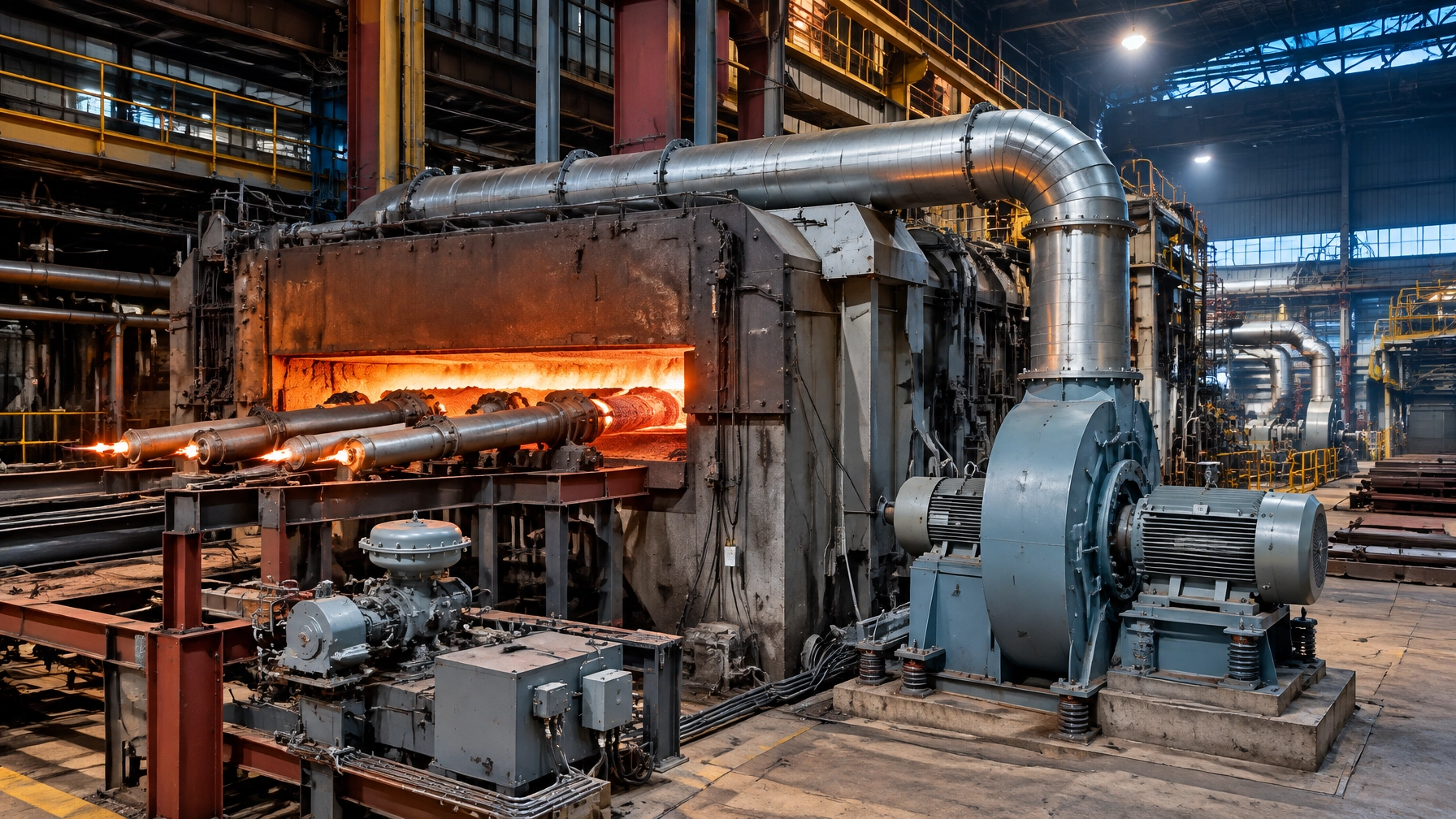
A fan’s certified curve describes a defined test arrangement. Its installed performance changes when real inlet and outlet connections create swirl, turbulence or pressure loss. AMCA Publication 201 calls the difference system effect. It is not a minor drafting issue: it changes the fan curve and the delivered operating point. [4]
AMCA’s worked example considers a fan selected for 15,000 cfm at 6.0 in. w.g. An inlet system effect costs 0.70 in. w.g., while an elbow mounted directly on the outlet adds 0.53 in. w.g. The fan then delivers about 13,975 cfm at 5.21 in. w.g., a 7 percent flow deficit. Raising fan speed from 1,205 to 1,294 rpm restores the target in the example, but shaft power rises from 19.7 to 23.6 bhp. Correcting the duct layout can therefore protect both throughput and fan energy.
Use AMCA’s rules of thumb as a starting point during design reviews:
- Provide at least 3 to 5 duct diameters of straight run on the inlet where practical, and avoid inlet swirl.
- Provide at least 2.5 duct diameters of effective straight outlet duct.
- At outlet velocities above 2,500 fpm, allow one additional duct diameter for each additional 1,000 fpm when estimating effective outlet duct length.
A furnace that cannot reach design throughput, or whose fan speed has been raised twice in ten years, merits a system-effect review before another speed increase. Check fan curves, installed connections, duct transitions, elbows and obstructions. When selecting replacement or new fans, Fan Energy Index (FEI) under AMCA Standard 208 is a useful comparative selection metric. It rewards efficient selection at the specified duty point; it does not remove the need to verify the installed system.

Damper versus variable speed
The fan affinity laws describe how fan duty changes with speed:
- Flow varies approximately with speed.
- Pressure varies approximately with the square of speed.
- Power varies approximately with the cube of speed.
Throttling with a damper increases system resistance while the fan continues turning at full speed. The fan spends energy pushing air against the restriction. Reducing fan speed instead can reduce power sharply under suitable conditions because of the cube relationship. This is the core efficiency case for a variable-speed drive (VFD) on forced-draft and induced-draft fans.
The decision still depends on operating duty. A fan that must run near constant volume may have limited opportunity for speed reduction. A VFD installation also requires checks of the fan’s minimum permissible speed, motor and drive suitability, and torsional or resonance behaviour across the speed range. The furnace pressure-control loop must remain stable as fan response changes. Calculate the business case from measured duty, operating hours and electricity consumption rather than applying an assumed savings percentage.
Reliability: reading the fan before it reads you
Vibration provides an early warning of fan condition, but readings need context. ISO 20816-3:2022 describes severity zones for industrial machines above 15 kW, using broadband velocity in mm/s rms at bearing housings: Zone A is typical of new machines, Zone B supports unrestricted long-term operation, Zone C indicates limited operation and planned repair, and Zone D signals risk of damage. [5]
For machines above 300 kW, approximate zone boundaries are:
- Rigid support: 2.3, 4.5 and 7.1 mm/s rms.
- Flexible support: 3.5, 7.1 and 11.0 mm/s rms.
These published values are guidance, not universal alarm settings. Apply the correct machine group, support condition and measurement location, and establish a commissioned baseline.
On an induced-draft fan, fouling and blade erosion can create mass imbalance. A dominant once-per-revolution (1X) component in the vibration spectrum is a useful diagnostic clue. Bearing temperature is a separate, often later indicator. Internal bearing defects require spectral or envelope analysis because broadband severity limits do not establish component health. Dusty-service fans deserve particular attention: deposited material changes balance, while erosion changes blade geometry and efficiency. Trend vibration and inspect the wheel rather than waiting for temperature or process performance to deteriorate.
Measurement quality is the real control loop
A control system cannot correct a ratio accurately when the airflow signal is unreliable. Air is often measured near the fan inlet or downstream of an air preheater, where straight run is short, velocity may be low and particulate is present. These are difficult measurement conditions, not reasons to accept a weak signal.
A dependable arrangement may require:
- Multipoint self-averaging pitot arrays to represent a distorted or uneven velocity profile.
- Flow conditioning where the available straight run cannot establish a representative profile.
- A low-range multivariable transmitter with pressure and temperature compensation to infer mass flow reliably.
- Instrument-range selection that preserves useful resolution at low flow, with checks for zero drift.
- A purge arrangement where particulate can plug sensing ports. During automatic purge, the control system may hold the last valid signal, so purge duration and signal handling must be understood.
- Planned calibration and verification intervals based on service conditions, instrument drift history and manufacturer guidance. Calibration should verify the complete measurement chain, not only the analyzer or transmitter in isolation.
Oxygen trim can be a useful layer, but it is not a substitute for sound airflow measurement or correct sampling-point placement. The ratio should be confirmed against independent measurements and process evidence.
Air-side discipline across operations
Air-side discipline improves fuel control and fan reliability across a steel rolling mill, heat treatment furnaces, an aluminum melting furnace, a melting furnace for steel, and a metal recycling furnace. The same engineering principles inform thermal processing equipment for a hot dip galvanizing plant and processes in the wire and cable industry. As an industrial furnace manufacturer, Continental Furnaces applies this system-level view to customized industrial furnace systems, where airflow measurement, fan duty and maintenance access must work together.
Keep the air side stocked
The right furnace spare parts reduce the time between detecting a fault and restoring reliable operation. Stocking should reflect the actual fan arrangement, instrument type, lead times and consequence of downtime. Consider a risk-based list that may include:
- Fan bearings, coupling elements, belts where fitted, and approved lubrication items.
- Damper bearings, linkage components, actuator spares and position-feedback devices.
- Differential-pressure transmitter components, impulse-line fittings, pitot-array seals and purge-system parts.
- Compatible oxygen-probe consumables and calibration gases.
- Inlet filter media, duct gaskets and expansion-joint materials appropriate to the service.
Maintain verified specifications and compatibility details with the inventory. Continental Furnaces provides a range of furnace spares and accessories intended to support reliable operation and responsive replacement.

Five-phase roadmap for air-side improvement
-
Baseline airflow and ratio survey: Record burner fuel flow, air-flow indication, flue-gas oxygen and combustibles at representative load points. Document fan speed, pressure, damper positions and relevant temperatures. Confirm that sample readings represent combustion products rather than leaked-in air.
-
Control architecture decision: Compare the existing positioning scheme with the process’s load variation and measurement capability. Retain simple control where it is demonstrably adequate; evaluate oxygen trim or fully metered control where drift, variable duty or flow uncertainty compromises efficiency.
-
Instrumentation and duct remediation: Correct poor inlet and outlet geometry, reduce avoidable system effect, address blockage and leakage, and specify suitable airflow measurement. Review transmitter range, compensation, purge needs and sample-point placement before installing new controls.
-
Commissioning and calibration baselines: Verify air and fuel measurements, establish ratio settings across the operating range and document baseline fan vibration, speed, power and pressure. Confirm performance at operating air temperature when applicable. Treat instrument calibration and mechanical linkage checks as part of commissioning.
-
Condition monitoring and quarterly ratio verification: Trend fan vibration and inspect dusty-service wheels for fouling or erosion. Verify air-to-fuel ratio at least quarterly as a practical starting interval, then adjust the interval to operating experience, process risk and instrument stability. Recheck after major maintenance, duct changes or fan work.
Build an enduring air-side partnership
A furnace that still holds temperature can conceal substantial air-side losses. A measured survey of ratio control, airflow instrumentation and fan installation identifies whether the priority is calibration, measurement improvement, duct correction, drive control or reliability maintenance. The objective is sustained throughput, dependable combustion and stronger lifecycle value, not a one-time adjustment.
Continental Furnaces brings 35+ years of expertise, ISO-certified quality and customized solutions to industrial thermal processing projects. Request a technical discussion and project quotation through our request-for-a-quote page. Make the air side a deliberate step toward sustained competitive advantage.
References
- U.S. Department of Energy, “Check Burner Air to Fuel Ratios,” Process Heating Tip Sheet #2, November 2007. https://www.energy.gov/sites/prod/files/2014/05/f16/check_burner_air2.pdf
- Carpenter, Kissock and D’Antonio, ACEEE Summer Study on Energy Efficiency in Industry, 2007. https://www.aceee.org/wp-content/uploads/proceedings-1980-2020/2007/08_2_116.pdf
- Air Monitor, “Unlocking Cost Savings: Improved Airflow Control in Industrial Combustion with a Fully Metered System.” https://www.airmonitor.com/industrial/wp-content/uploads/sites/3/AMC-Whitepaper_Combustion-2022.pdf
- AMCA International, “System Effects: AMCA Pub. 201 – Changing the Curve.” https://www.amca.org/assets/resources/public/assets/uploads/System_Effects_AMCA_Pub._201_Changing_the_Curve_POP_UP_04202020.pdf
- ISO, ISO 20816-3:2022, Mechanical vibration – Measurement and evaluation of machine vibration. https://www.iso.org/standard/78311.html