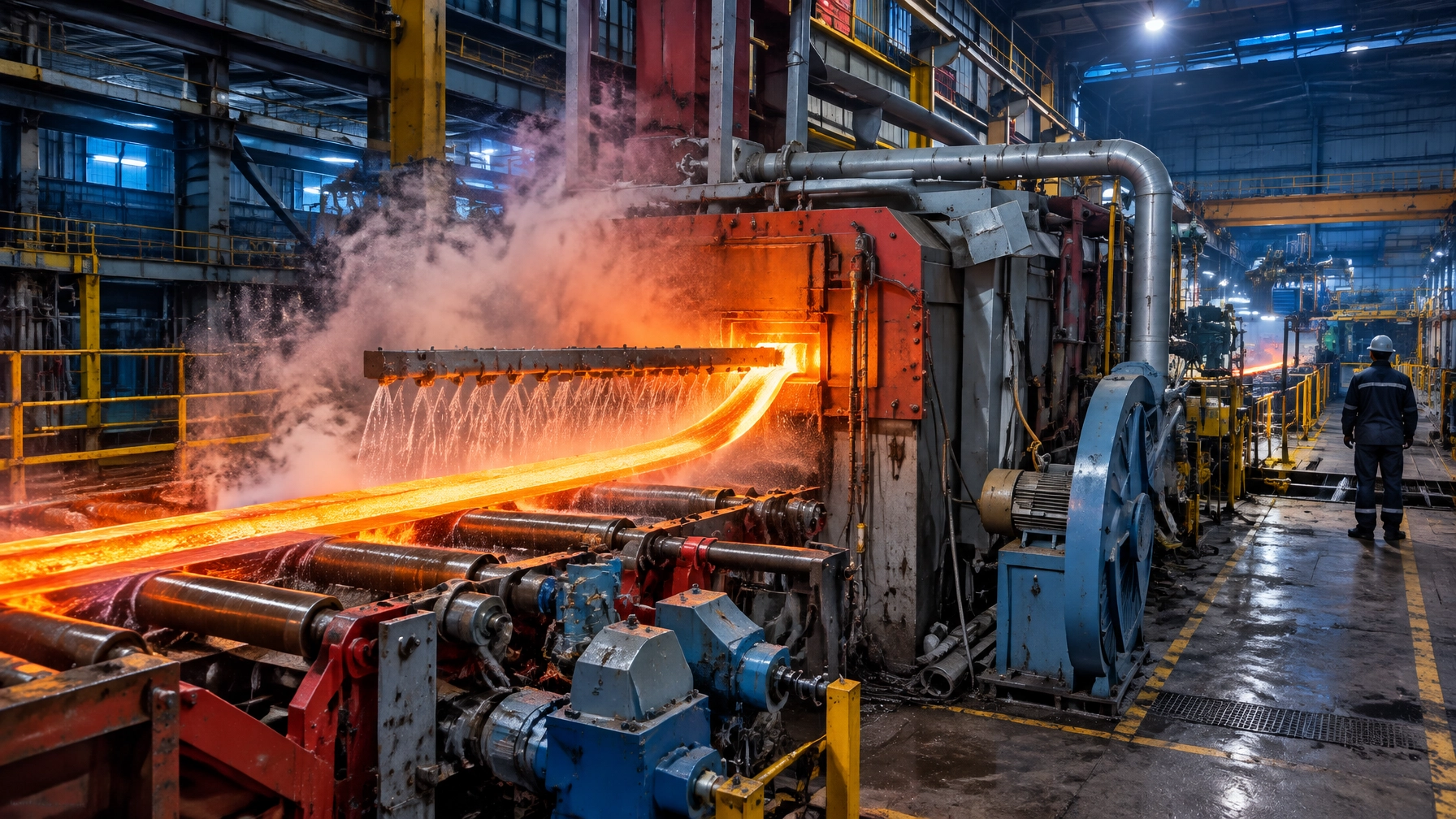
A reheat furnace does not begin its work at the charging door. Its thermal history starts at the meniscus, where steel first meets the mould, and continues through casting, cutting, transport and charging.
Plants often manage the caster, furnace and steel rolling mill as separate assets. Yet many important energy and yield losses develop in the 30 to 300 metres between the mould and the furnace: strand consistency, crop length, transfer time, charge temperature and buffer logic.
That is why furnace KPIs such as kcal/kg or kWh/t, scale loss and temperature uniformity are partly decided upstream. The furnace is the last thermal variable in a chain that starts at the meniscus.
Why the furnace is the last thermal variable in the chain
The material path is straightforward: meniscus → mould → secondary cooling → strand → torch cut → crop → transfer table → charging → soaking → rolling. Each stage adds or removes variation that the furnace must absorb. A furnace cannot repair an inconsistent shell, recover the heat lost during a three-minute delay, or make a 480°C slab behave like one that arrived at 700°C.
The furnace inherits four critical variances:
- Temperature across the strand width, shaped by mould heat transfer and spray distribution.
- Surface-to-core temperature gradient, influenced by solidification and cooling history.
- Length and crop variation, affecting furnace loading and rolling yield.
- Arrival-time variation, which disrupts furnace residence time, zone loading and mill rhythm.
The practical consequence is clear: optimise the whole thermal chain, not just burner settings.
Caster-side thermal discipline
Caster-side maintenance is a thermal-control programme. Small, repeatable deviations in mould practice, sprays and alignment accumulate into inconsistent furnace charge conditions.
Mould heat transfer, oscillation and flux
Mould oscillation is commonly configured within a 3 to 10 mm stroke and 60 to 300 cycles per minute, depending on casting speed and section. A 60 to 80% negative strip ratio is a common target range. Shorter negative strip time, achieved through a higher frequency and lower stroke, can reduce oscillation-mark depth and transverse-crack risk. It must remain balanced against adequate flux consumption and lubrication. The MDPI oscillation-mark study discusses the relationship between oscillation conditions and surface marks.
A useful mould-flux consumption benchmark is 0.3 to 0.6 kg/m² of mould surface area. High consumption can indicate instability; low consumption can point to inadequate lubrication. Track the trend alongside casting speed, grade and mould temperature rather than treating one reading as a standalone diagnosis.
Mould copper plate life varies with water quality, taper and grade mix. Indicative supplier and plant figures include 100 to 150 heats for chromium-plated plates, around 300 heats for nickel-plated plates, and up to roughly 650 heats for modern billet mould designs. These figures are planning references, not guaranteed service intervals.
Secondary cooling and nozzle health
Specific secondary-cooling water is often in the range of 0.9 to 1.7 l/kg, depending on section, speed and grade. The total flow matters less than whether each nozzle delivers the spray pattern required by the metallurgical model.
A practical nozzle-flow deviation tolerance is ±15%. Confirm that sprays strike the strand, not the support rolls. Clogging, misalignment or an incorrect spray footprint produces uneven heat removal, risks internal cracks and creates inconsistent caster-exit temperatures. A structured field check and model comparison are central to the Lechler secondary-cooling audit paper.
For beam blank, bloom and round casters, air-mist cooling gives operators finer control of the cooling curve through the straightener region and generally reduces water consumption compared with water-only cooling.
Mechanical alignment is a thermal parameter
Set roller alignment within ±0.3 mm across the strand and match roll gaps to the caster map within ±0.2 mm. Bearing temperature alarms are typically set around 85°C. Misalignment can appear as bulging, off-corner depressions and slab rhomboidity. Downstream, those defects present as uneven furnace heating, steering difficulties and camber at the mill.
Alignment tolerances are thermal tolerances, not maintenance niceties. High-performing plants target caster availability above 92%, while sequence casting limits start-stop losses and supports stable downstream scheduling.
Breakout prediction and the cost of a stop
Mould thermocouple arrays combined with LSTM, fuzzy-logic or gradient-boosting models can provide roughly 30 to 120 seconds of warning of a sticker or bleeder. That warning window supports timely intervention and helps protect sequence continuity.
A breakout is not only a caster loss. It can mean a lost sequence, cropped slab and a furnace suddenly operating with a different charge mix and temperature profile. The disruption affects furnace efficiency and mill throughput as much as caster performance.
Comparative table 1: The charging mode decision
| Charging mode | Typical charge temperature | Reheat energy demand | Scale loss | Logistics requirement | Best suited to |
|---|---|---|---|---|---|
| Cold charge | Ambient, typically about 20°C | Roughly 375 to 640 kWh/t, or 1.4 to 2.2 GJ/t | Highest exposure due to longer time at temperature | Flexible storage and conventional material handling | Mixed schedules, long storage or distant caster |
| Warm charge | Approx. 400 to 700°C | Lower than cold charge; depends on entry temperature and furnace model | Reduced versus cold charge | Coordinated dispatch and controlled storage | Plants establishing a hot-charge programme |
| Hot charge | Approx. 700 to 900°C | Substantially reduced; reheat and soaking still required | Lower through reduced time at temperature | Fast transfer, covered routes and sequence coordination | Integrated caster and mill operations |
| Direct charge / direct rolling | Above approx. 1,000°C | At around 1,100°C, about 25 to 55 kWh/t for soaking | Lowest reheat exposure, subject to operating conditions | Close process integration and tightly matched production | Suitable near-net-shape and directly connected lines |
These are indicative benchmarks from published energy studies and vary by furnace type, section, grade and mill configuration. Cold-charge and direct-charge ranges are drawn from published assessments of hot and cold rolling energy, including the Umweltbundesamt study. The hot-charging energy and logistics overview also explains why transfer and scheduling determine how much of the theoretical benefit becomes actual plant performance.
The transport leg nobody measures
A roller conveyor can cool exposed steel at roughly 6 K per minute on average. A slab in a stack cools much more slowly, around 0.15 to 0.63 K per minute, depending on position. In practical terms, a 10-minute conveyor delay can cost more temperature than a 40-minute wait in a covered stack. Many hot-charge schemes target transfer times under 10 minutes to hold charge temperatures above 700°C.

Prioritise these logistics controls:
- Use covered or insulated transfer where practical.
- Select the shortest practical route between caster and furnace.
- Confirm crane and charging-machine availability before casting the sequence.
- Match charger cycle time to caster sequence and cut rate.
- Establish direct communication between caster and furnace pulpits.
Published reheat models indicate that a 100°C increase in charging temperature is worth roughly 0.086 MMBtu/t, or about 0.022 Gcal/t, of fuel. Convert that saving using the plant’s own fuel price and actual charge mix, not a generic currency assumption.
There is a scheduling trap that shows up in almost every hot-charge business case. The constraint is rarely the caster and rarely the furnace; it is the charging machine cycle and the crane. A charger that needs 90 seconds per slab cannot absorb a caster delivering one every 60 seconds, so the surplus sits on the conveyor losing roughly 6 K per minute. Before any capex, measure charger cycle time against cut rate. If the charger is the bottleneck, the money belongs there rather than in a larger furnace.
Be equally honest about which grades belong on a hot-charge route. Products needing full surface inspection, certain exposed automotive panels and some high-alloy grades are often cold charged deliberately, because the inspection and conditioning step cannot be compressed. A hot-charge programme that assumes the entire mix can move hot will look attractive on paper and fail in the scheduling meeting.
What the furnace has to be able to do
Walking beam, buffer and temperature setpoint
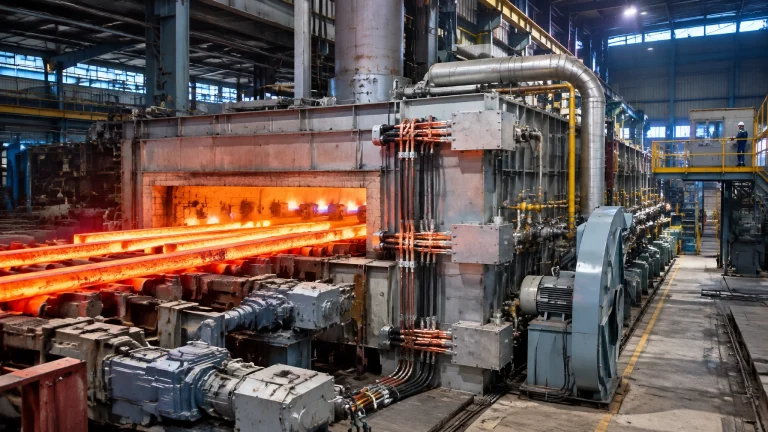
A walking beam furnace serves as a buffer between a continuous caster and a batch-paced mill. Charge temperature changes the required zone setpoints and residence time. The furnace model must therefore be retuned for each charging regime, not left on its cold-charge curve. This is essential for robust industrial furnace systems designed to handle variable charge conditions.
Skid-pipe cooling losses typically account for 10 to 15% of total furnace fuel consumption. A supplier-published ArcelorMittal Bremen case reports lightweight skid insulation reducing energy loss by as much as about 35% versus traditional fibre modules. Verify the opportunity against the plant’s own stack test and cooling-water measurements before projecting savings. See the ArcelorMittal Bremen skid insulation paper.
Recuperation also warrants a measured assessment. Improving recuperator effectiveness from 37 to 50% cuts specific heat consumption by roughly 6%; reaching 70% corresponds to roughly 9.5%. A hot-charge line makes this review particularly important: firing rates are lower, so every percentage point of stack loss becomes a larger share of a smaller fuel bill.
Furnace length and zone split deserve the same scrutiny. A furnace sized for cold charging carries excess residence time for a hot-charge mix, and excess residence time at temperature is paid for twice: once in fuel and again in scale. Where the caster-to-mill link is being tightened, the more valuable question is not how to fire harder but how to shorten the effective soak without losing the core-to-surface uniformity the mill needs at the first finishing stand. That is a control-model and zone-segmentation exercise as much as a brick-and-burner one.
Heat treatment furnaces and reheat furnaces have different duty cycles, but both require a furnace design and control strategy matched to the actual temperature-time profile.
Edge and corner compensation
Induction edge heaters or edge burners can restore slab-edge temperature before roughing when transit or water-cooled skid zones have chilled the edges. Edge and corner temperature is a mill problem before it is a quality problem: cold edges increase rolling loads, worsen camber and contribute to edge cracks in finishing stands.

Comparative table 2: Caster-to-furnace audit parameters
The following figures are indicative benchmarks drawn from published surveys, plant reports and supplier references. Values vary by section, grade, casting speed, furnace type and mill configuration.
| Parameter | Benchmark target | Action limit | Consequence of drift | Owner |
|---|---|---|---|---|
| Mould oscillation negative strip ratio | 60 to 80% | Outside target range | Deeper marks or lubrication and crack risk | Caster process |
| Mould flux consumption | 0.3 to 0.6 kg/m² of mould surface area | Outside range or unstable trend | Lubrication or mould stability concern | Caster operations |
| Secondary cooling water flow per nozzle | 0.9 to 1.7 l/kg system-specific | Deviation from metallurgical model | Uneven solidification and exit temperature | Caster process |
| Nozzle flow deviation | Within ±15% | Beyond ±15% | Uneven heat removal and crack risk | Caster maintenance |
| Roller alignment | Within ±0.3 mm across strand | Outside tolerance | Bulging, surface variation and slab shape defects | Mechanical maintenance |
| Roll gap versus caster map | Within ±0.2 mm | Outside tolerance | Rhomboidity and downstream steering issues | Mechanical maintenance |
| Bearing temperature | Alarm typically around 85°C | Alarm threshold reached | Bearing failure risk and alignment drift | Mechanical maintenance |
| Strand surface temperature at caster exit | Grade and model profile | Deviation from grade-specific profile | Uneven furnace charge and mill heating | Caster process |
| Transfer time | Under 10 minutes for many hot-charge schemes | Above planned time or charge threshold lost | Charge temperature drop and higher reheat demand | Material handling |
| Charge temperature | Above 700°C for hot charge | Below hot-charge threshold | Higher firing demand and longer heating | Furnace operations |
| Furnace zone spread | Retuned to charge regime | Deviation from product model | Uneven soaking and rolling temperature | Furnace operations |
| Skid cooling loss | Typically 10 to 15% of furnace fuel | Above plant baseline or target | Fuel loss and skid marks | Furnace maintenance |
Yield economics that the furnace and mill share
Continuous-casting yield losses typically run 2 to 8%, corresponding to total yield of 92 to 98%. A published breakdown provides a useful checklist: head and tail crop losses of 1.3 to 3.3%, scarfing and surface conditioning of 0.5 to 1.5%, quality downgrades of 0.5 to 2.0%, and length tolerance losses of 0.2 to 0.5%.
Crop length is determined by caster practice but paid for by the whole chain. Scale loss is influenced by furnace atmosphere and time at temperature. Downgrades often originate in caster surface quality. A plant that only measures yield at the weighbridge cannot allocate these losses or assign effective improvement actions.
Put three numbers on one shared dashboard:
- Cast-to-rolled yield
- Specific reheat energy per tonne charged
- Share of heats charged above the hot-charge threshold
This shared view makes the circular-economy case practical: fewer unnecessary crops, less scarfing, lower scale loss and more saleable steel from each cast tonne.
2026 technology and market updates
- AI breakout prediction and crop optimisation: Dynamic crop lengths and scarfing depths use real-time solidification and surface data instead of fixed allowances.
- In-situ TDL combustion analysis: Tunable diode laser analysers measure O2, CO and CH4 in the radiant section, supporting tighter air-fuel trim in place of extractive sampling. Vendor and case-study claims include excess-O2 trim from 6% to 2%, 6 to 9% fuel savings with CO-based trim, and 10 to 15% in some fired-heater cases. The DOE/OSTI combustion diagnostics report describes in-situ measurement and control development.
- Flame safeguard discipline: Modern burner-management design expects flame-failure response within about 4 seconds. IR scanners require attention to vibration, heat and background refractory radiation; UV scanners are common on gas burners.
- Condition-monitoring convergence: Track combustion and cooling-air fan vibration against ISO 10816 thresholds, investigate above about 4.5 mm/s RMS and act immediately above about 7.1 mm/s. Acoustic imaging identifies compressed-air, gas and sealing-air leaks. One published overfire-air-fan case avoided roughly USD 376,000 in downtime, a case study rather than a universal expectation.
- Digital twin and charge-mix scheduling: Feed caster sequence data into furnace models to predict arrival temperature and pre-position zone setpoints.
- Long-horizon transition: Electrification and hydrogen-readiness become more valuable as firing and carbon costs rise, increasing the value of the caster-to-mill thermal buffer.
- Emissions and quality together: Tighter consents and pressure to lower scale loss and NOx make furnace atmosphere and charge temperature a joint review, not separate projects.
Continuous annealing lines in the wire and cable industry face a related challenge: process stability depends on consistent material temperature and well-coordinated line speed.
A four-phase roadmap
Phase 1: Thermal chain mapping, weeks 1 to 4
Log charge temperature, transfer time and furnace energy per charge for four weeks. Many plants find their real hot-charge ratio sits well below the nameplate figure.
Phase 2: Caster-side discipline, no capex, months 1 to 3
Complete a nozzle audit, review oscillation parameters, align rollers to the caster map, trend mould-flux consumption and reassess crop length. This is often the cheapest yield improvement in the plant.
Phase 3: Transport and furnace adaptation, months 3 to 9
Review transfer route and covering, charger-cycle matching, furnace model settings for hot charge, skid insulation and recuperator performance. Add edge heating where mill requirements justify it.
Phase 4: Sustained integration, month 9 onward
Maintain one dashboard for cast-to-rolled yield, energy per tonne and charge-temperature distribution. Hold critical furnace spare parts for the charger, fans, scanners and nozzles, and schedule quarterly thermal audits.
Build an enduring caster-to-mill partnership
Continental Furnaces brings 35+ years of experience designing and building heat treatment furnaces, melting furnaces and recycling projects, galvanizing and pickling plants, and supplying furnace spares and accessories. As an industrial furnace manufacturer, we work with rolling-mill and caster operators on the thermal performance of the chain, not simply on the equipment box.
The same engineering discipline supports a melting furnace for steel, an aluminum melting furnace or a metal recycling furnace. Continuous-line thermal control also matters in a hot dip galvanizing plant, where stable furnace operation supports coating quality and productivity. Our wider portfolio includes heat treatment furnaces and melting furnaces and recycling projects, with tailored thermal processing equipment for varied industrial duties.
Start with a thermal-chain review of caster conditions, transfer logistics, charge-temperature distribution and furnace performance. Request a consultation with Continental Furnaces and take a strategic step toward sustained competitive advantage.