Afternoon Edition: 5 October 2026
In every modern furnace, combustion hardware generates heat, but the control system decides how efficiently, safely and repeatably that heat is delivered. Burner management, air/fuel ratio control, oxygen trim, furnace pressure, temperature measurement and data integrity form the operating brain of the installation.
For plant managers, maintenance heads and process metallurgists, this creates a clear mandate: treat instrumentation and automation as engineered production assets, not background utilities. Drift in a thermocouple, a sticky control valve or a contaminated oxygen probe can increase fuel consumption, trigger nuisance trips and compromise metallurgy long before the failure becomes visible.
Continental Furnaces applies more than 35 years of thermal-processing expertise to heat treatment, melting, galvanizing and rolling mill applications. The objective is enduring lifecycle performance: lower fuel cost, safer operation, higher yield and documented quality.
Why Control Accuracy Governs Cost, Emissions and Quality
A furnace control strategy must balance thermal demand, combustion completeness and process atmosphere.
- Excess air versus CO: Too little air increases CO, soot and flame instability. Too much air carries heated gases up the stack. A practical business-case screen is that excess-air drift can reduce efficiency by 2–6%, depending on furnace design and operating load.
- Heat treatment atmosphere: In heat treatment furnaces, dew point, oxygen potential and carbon potential must remain stable. A temperature profile can be correct while an uncontrolled atmosphere produces decarburization, oxidation or inconsistent hardness.
- Hot dip galvanizing: A hot dip galvanizing plant requires stable bath temperature, strip speed and immersion conditions. A typical zinc-bath starting range is approximately 450–470°C, subject to alloy, coating specification and plant design.
- Aluminum melting: In an aluminum melting furnace, excess heat and poor flame control increase oxidation and dross. Melt temperature is commonly managed within an alloy-specific operating window, often around 660–750°C, while avoiding unnecessary superheat.
- Steel melting: A melting furnace for steel may operate near 1,500–1,650°C, making reliable thermocouples, pyrometers, flame supervision and cooling circuits essential.
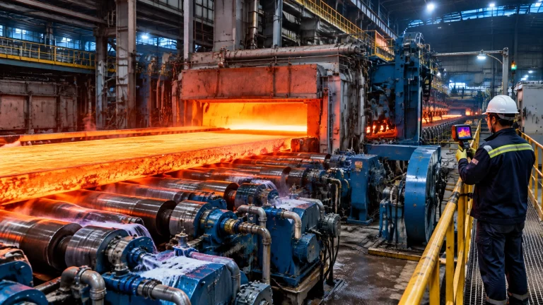
- Steel reheating: In a steel rolling mill, zone-to-zone control protects discharge temperature and rolling consistency. A strip temperature uniformity error of ±15°C can become a direct source of scale, dimensional variation and downstream defects.
- Wire and cable industry: Continuous annealing and heating lines require synchronized burner, line-speed and tension control. A temperature loop that lags the production recipe quickly becomes a yield problem.
The U.S. Department of Energy’s process heating resources also identify burner air/fuel verification, furnace pressure control, heat recovery and air infiltration reduction as practical efficiency measures.

The Most Expensive Control Failure Modes
Sensor and measurement failures
- Thermocouple degradation or decalibration: Oxidation, mechanical damage and insulation breakdown create slow bias or intermittent signals.
- RTD and pyrometer errors: Loose terminals, emissivity assumptions and dirty sight paths can produce credible but incorrect readings.
- Fouled oxygen probes: Scale, dust or condensate can bias oxygen readings. Air ingress at the probe or sampling line can make the system report falsely high oxygen and command unnecessary fuel reduction.
- Blocked impulse lines: Dust, condensate or corrosion can isolate pressure and flow transmitters from the process.
- Gas analyser contamination: Filter blockage, sample-line leaks and calibration-gas expiry cause unreliable CO, CO₂ or O₂ feedback.
Final-control and logic failures
- Valve stiction and actuator hysteresis: The command changes, but fuel or air flow does not respond until the valve breaks free.
- Incorrect valve characterisation: An equal-percentage valve configured as linear can create poor low-fire control and unstable ratio tracking.
- PLC/SCADA communication faults: A stale value, failed remote I/O rack or network drop can freeze a permissive, alarm or recipe parameter.
- Nuisance burner-management trips: Poorly sequenced purge logic, marginal flame scanners or incorrect interlock delays reduce availability and encourage unsafe bypass practices.
Common symptom-to-cause evidence includes:
- Rising fuel use with stable production → excess-air drift, air leakage or fouled heat-recovery surfaces.
- O₂ reading high while CO also rises → probe air ingress, sampling fault or incomplete combustion.
- Oscillating temperature and valve position → excessive controller gain, stiction or incorrect valve sizing.
- Repeated flame failure at low fire → scanner alignment, unstable turndown or low gas-pressure margin.
- Zone temperature disagreement of 10–15°C → thermocouple drift, poor placement, refractory damage or uneven burner distribution.
Calibration and Maintenance Intervals
Intervals must be confirmed against the OEM manual, risk assessment, local regulation and the site quality system. The following schedule is an engineering starting point.
Shift or daily
- Review burner trips, flame-signal strength, furnace pressure and fuel/air trends.
- Check visible flame condition, unusual noise, leaks and stack appearance.
- Verify temperature deviation, oxygen trend and alarm status.
- Confirm purge, ignition and shutdown events are recorded.
Weekly
- Inspect flame scanners, sight glasses, sample lines and analyser filters.
- Check impulse lines for condensation or blockage.
- Compare critical display values with a portable reference.
- Review control-valve travel, actuator air pressure and abnormal cycling.
Monthly
- Verify air/fuel ratio at low, medium and high fire.
- Perform a combustion analyser cross-check and record O₂, CO and temperature.
- Check thermocouple terminals, compensation cables and enclosure integrity.
- Test selected permissives without defeating the safety function.
Quarterly
- Calibrate pressure and flow transmitters against traceable references.
- Validate oxygen probes and gas analysers using certified gases.
- Conduct control-loop performance review: overshoot, settling time, oscillation, valve travel and output saturation.
- Verify furnace pressure control, typically starting near +1 to +5 Pa positive pressure where the furnace design permits.
Annual or planned outage
- Replace or recalibrate degraded thermocouples, RTDs and flame scanners.
- Complete full BMS functional testing, including purge, flame failure, fuel shutoff, low-air and high-pressure trips.
- Test safety interlocks using approved procedures and document proof-test results.
- Inspect control valves, linkages, dampers, burner tiles, refractory and oxygen-probe assemblies.
- Review PLC, HMI, drive and field-device obsolescence.
Practical tuning benchmarks
Use these numbers as starting points, not universal acceptance criteria:
- Verify air/fuel ratio across at least three firing points, including minimum stable fire.
- Consider flue-gas oxygen trim starting ranges of 2–4% O₂ for many gas-fired systems; heat treatment atmospheres and burner designs may require different values.
- Keep furnace pressure slightly positive where appropriate to limit uncontrolled air ingress.
- Confirm turndown without flame lift, flashback, unstable CO or excessive temperature deviation.
- Track TSAT, temperature setpoint attainment time, alongside overshoot, settling time and steady-state deviation.
- Require documented purge timing and air-change calculations; never copy a timer without confirming furnace volume and approved safety design.

Quick-Reference Control Health Checklist
- Temperature deviation: investigate sustained errors above ±5–10°C from the approved process band.
- Furnace pressure: trend the value continuously; unexplained movement indicates leakage, damper or fan problems.
- O₂ trend: investigate sudden changes greater than 0.5–1.0 percentage point without a production-load explanation.
- CO trend: treat any sustained increase as a combustion or measurement investigation, not merely an alarm to acknowledge.
- Valve travel: excessive hunting or long periods above 90% output indicate sizing, pressure or tuning issues.
- Flame scanner: confirm stable signal at ignition, low fire and high fire.
- Recipes: lock approved setpoints, atmosphere limits, ramp rates and alarm limits with revision control.
- Data: retain time-stamped records for temperature, pressure, O₂, CO, fuel flow, trips and operator changes.
Legacy Practice Versus the 2026 Automation Model
The figures below are business-case screening benchmarks for project evaluation, not guaranteed values.
| Metric | Legacy control practice | 2026 automation model |
|---|---|---|
| Fuel-use opportunity | Baseline; often 5–12% avoidable loss | Typically screens for 5–15% reduction |
| Temperature uniformity | Approximately ±15–25°C in poorly maintained zones | Target screening range of ±5–10°C |
| Alarm handling | Reactive, alarm floods and manual logs | Prioritised alarms, historian trends and root-cause dashboards |
| Calibration method | Periodic manual checks with incomplete records | Traceable digital certificates and condition-based verification |
| Spares strategy | Emergency replacement after obsolescence | Criticality matrix, lifecycle register and stocked furnace spare parts |
| Labour requirement | High manual rounds and troubleshooting | Fewer routine rounds, higher-value reliability work |
| Payback | Often undefined | Screening range of 12–36 months for targeted upgrades |
2026 Technology Updates for Industrial Furnace Systems
The 2026 model combines proven combustion engineering with connected data layers:
- Hydrogen-ready and hybrid fuel control: Burner management must account for flame speed, calorific value, gas train compatibility, leak detection and safe transition between natural gas, hydrogen blends, biogas or syngas.
- Advanced O₂/CO trim: Dual feedback prevents the system from chasing oxygen alone while CO rises.
- Model-predictive control: Furnace load, line speed, thermal inertia and zone interaction are used to anticipate demand instead of reacting late.
- Digital twins and simulation: A validated furnace model supports recipe testing, energy studies and operator training before production changes.
- OPC-UA and MQTT data layers: Open communication connects PLC, SCADA, historians, laboratory systems and enterprise dashboards without creating isolated data silos.
- Edge analytics: Local anomaly detection identifies valve stiction, probe fouling, rising fuel intensity and abnormal flame behaviour before a trip.
- Automated recipe traceability: Approved recipes, batch identity, operator actions and deviation records create an auditable quality trail.
- Remote diagnostics: Secure service access shortens troubleshooting time while preserving plant cybersecurity.
- Safety alignment: BMS and safety instrumented functions should be engineered with reference to IEC 61511 and ISO 13577-style industrial furnace safety practice.
- OT cyber-hygiene: Segment networks, control privileges, back up PLC programs, manage removable media and maintain an asset inventory.
- Obsolescence management: Track PLCs, drives, HMIs, flame relays, transmitters and communication modules before support ends.

A Five-Phase Reliability Roadmap
Phase 1: Assessment and Planning
- Define fuel, quality, safety and production KPIs.
- Map burners, instruments, control loops, interlocks and data paths.
- Rank risks by downtime, safety consequence and product impact.
Phase 2: Baseline and Instrument Integrity
- Establish fuel-per-tonne, temperature uniformity and alarm baselines.
- Calibrate critical sensors and verify impulse lines, analysers and flame scanners.
- Separate measurement problems from genuine process problems.
Phase 3: Control Loop and Combustion Optimization
- Tune temperature, air/fuel, pressure and oxygen loops.
- Validate low-fire turndown and multi-zone response.
- Confirm CO remains controlled while excess air is reduced.
Phase 4: Spares, Obsolescence and Data Infrastructure
- Create a critical spares list for burners, valves, scanners, probes, PLCs and drives.
- Build secure OPC-UA/MQTT connectivity and historian tags.
- Store controlled backups of PLC, HMI and recipe programs.
Phase 5: Review and Continuous Improvement
- Review KPIs monthly and after every major maintenance event.
- Compare actual fuel intensity with the approved business case.
- Update recipes, alarm rationalisation, calibration intervals and training.
- Convert recurring failures into engineered corrective actions.
Build the Control System as a Long-Term Asset
A reliable furnace is not defined only by its refractory, burner capacity or steel shell. It is defined by the quality of the decisions made continuously by its sensors, logic, actuators and operators.
Continental Furnaces supports customers across heat treatment, steel rolling, melting, galvanizing, recycling and the wire and cable industry with customized thermal processing equipment, responsive service and lifecycle support.
Do not wait for rising fuel bills, unstable quality or repeated burner trips to reveal control-system weakness. Book a technical review with Continental Furnaces through our consulting team or contact page. A structured assessment of combustion, instrumentation and automation is an essential step toward safer operation, lower cost and sustained competitive advantage.