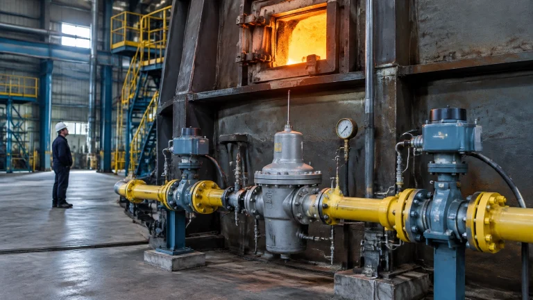

A furnace specification, acceptance test and energy review can stop at the burner flange. The equipment downstream, from outlet duct to stack top, is then managed as a service rather than as an asset. It may have no setpoints, no trend tags, no cycle register, no defined spare policy and no current drawing.
That gap can be expensive. Downstream air ingress can mislead the oxygen analyser and provoke the wrong burner correction. Ducts and stacks move with temperature, placing finite-life joints under cyclic stress. And a cold-end surface that falls below the gas dew point can turn a stack into a corrosion vessel. The exhaust path deserves the same design discipline as the furnace that feeds it.
Earlier analysis covered combustion air and flue-gas fan systems, including ratio-control architecture, system effect, damper versus VFD economics and fan vibration. Waste heat recovery, recuperative burners and combustion air preheating economics were covered separately, as were burner turndown and part-load behaviour. Furnace pressure control and shell-level air infiltration were also covered separately. This article picks up downstream of that, in the duct itself: the exhaust side from the furnace outlet flange to the stack top. The fuel gas train from meter to burner manifold was covered separately.
The numerical values below are a reading of published standards, manufacturer literature and published case studies. They are indicative and vary with furnace type, fuel, load pattern and installation. They are not a substitute for OEM instructions, the structural or installation standard of record, the authority having jurisdiction, or a site-specific engineering review.
The Boundary Problem: Where the Furnace Ends and the Duct Begins
ISO 13579-1:2013 sets out methods for measuring energy balance and calculating efficiency for industrial furnaces and associated processing equipment, including calculations and the requirements for an energy-balance evaluation report. Its boundary is the furnace and associated equipment, not the wider process beyond it. Part 2 applies the method to steel reheating furnaces; Part 3 applies it to batch-type aluminium melting furnaces. The balance sets total energy input, including fuel-equivalent energy and other inputs, against thermal output, auxiliary electrical equipment, utility generation and electrical loss. [1][2][3]
The boundary has a commercial consequence: losses in downstream ductwork and stack equipment can sit outside the calculated furnace efficiency while remaining inside the fuel bill. The literature on furnace energy performance and heat-balance losses makes the size of the wider opportunity clear, even when a furnace-level report passes its test. [4][5] Two facilities can report the same calculated efficiency while paying for different quantities of unaccounted exhaust-train loss.
A complete asset file should include:
- An as-built flue-path drawing with joint locations and movement budgets.
- A leak register with measured oxygen at each suspect section.
- A joint cycle count against its design life.
- A stack metal-temperature trend at the cold end.
- An inspection interval with written acceptance criteria.
Tramp Air Is Not Excess Air
An oxygen analyser measures oxygen at its probe. It cannot identify where that oxygen entered the gas stream. If ambient air leaks into a duct before the probe, the reading rises as though the burner supplied excess air. The trim loop can then cut burner air, making the flame richer than intended while the analyser settles on a normal-looking value. The fuel saved at the burner is spent heating cold air that never participated in combustion. This is engineering reasoning about probe location and control response, not a separate measured benchmark.
The diagnostic correction is to locate and seal the leak, not to tune the trim loop to conceal it. Two useful clues at steady firing are oxygen that does not respond to air-damper position and oxygen rising as furnace pressure becomes more negative. Neither is useful unless the trend is deliberately reviewed and readings are compared on both sides of suspect sections.
For natural gas, published combustion-efficiency tables show the combined effect of net stack temperature and oxygen concentration. At 2% oxygen, roughly 9.5% excess air, efficiency moves from about 85.4% at a net stack temperature of 200°F (about 93°C) to about 76.0% at 600°F (about 316°C). At 10% oxygen, roughly 81.6% excess air, the same temperature span takes efficiency from about 82.8% down to about 68.2%. [8]
The comparison matters because a diluted analyser reading can hide a genuinely poor burner condition, and because either variable alone can move the number. Published guidance puts the gain at roughly 1 percentage point of efficiency for every 40°F (about 22 K) of stack temperature reduction, or for a 15% reduction in excess air. Published examples also show substantial fuel savings when excess air falls from 20% to 5%, corresponding roughly to a change from 4% to 1% oxygen in the flue gas. But a duct leak is not excess air at the burner: correct the source before changing combustion settings. [7][8]
The Movement Budget Nobody Recalculates
Thermal growth is straightforward to calculate: change in length equals the coefficient of expansion multiplied by original length and temperature change. For carbon steel, a mean coefficient is about 12 × 10⁻⁶ per K. A 20 m duct therefore grows about 0.24 mm per K; a 50 K temperature rise produces about 12 mm of movement. The installed supports, guides, anchors and joints must let that movement occur where the design intends.
Anchoring a duct in three places converts a thermal-expansion problem into a stress problem. Movement has to go somewhere. If the joint cannot take it, the load transfers into a stiffener, flange or support. This is engineering reasoning; the actual load path depends on the as-built geometry and restraint conditions.
Joint selection starts with the movement directions and pressure conditions:
- Single joints accommodate axial movement.
- Universal joints use two bellows and a common connector to absorb combined axial, lateral and angular movement.
- Hinged joints use one bellows and hinge pins to allow rotation in one plane.
- Gimbal joints use a floating ring to allow angular rotation in any plane.
- Pressure-balanced and externally pressurised arrangements address particular pressure and movement requirements.
- Rectangular joints suit duct geometries where a circular element is not appropriate.
EJMA standards provide the design basis for metallic bellows expansion joints. [9] The nameplate and design record should state the intended movement, pressure conditions and cycle life. Bellows are designed to work in the plastic range of their material; their design life is finite and stated in cycles. Fatigue life depends on the total stress range from pressure plus deflection. A joint that has consumed its cycle life cannot be inspected back into service: fatigue damage develops in the bellows wall and may not be visible until a crack appears. A cycle register matters more than appearance alone.
Squirm is a pressure-induced instability and a hard ceiling, not a gradual leak limit. Column squirm is gross lateral bowing, similar to buckling of a slender column, associated with high length-to-diameter ratios. In-plane squirm is the tilting or warping of individual convolutions under high meridional bending stress. Neither failure is cured by specifying stronger material. A design optimised for high cycle life generally has a lower squirm pressure limit, so flexibility, pressure capacity and fatigue life must be balanced at design stage. Exceeding the squirm limit risks sudden loss of shape.
The Flex Element Is a Spare Part With a Temperature Stack

A fabric expansion joint is a multi-layer laminate, not a single material with one temperature rating. A PTFE-glass sealing face has a continuous limit of about 300°C. To handle flue gas at 800 to 1,100°C, the assembly uses internal high-silica glass and ceramic-fibre insulation layers to shield its structural and sealing layers. Service life depends on sizing that insulation stack through a heat-transfer calculation for the actual duct environment.
Two common failure mechanisms deserve deliberate checks. Flutter from turbulence or pressure fluctuation near fans and dampers fatigues fabric and can tear it. Thermal damage can occur where cover temperature exceeds about 60°C, or where inadequate ventilation prevents heat from dissipating. Look for discoloration, whitening, peeling coatings, blistering, cracks and deformation. Thermal imaging can find hidden hot spots before visible damage develops.
Fluid Sealing Association guidance emphasises installation and inspection discipline. [10] Before and after installation:
- Confirm the joint design; check that duct flanges are smooth, clean and continuously welded.
- Verify alignment and flow orientation.
- Protect fabric from sharp edges and welding spatter; never walk on the joint.
- Remove shipping straps before start-up.
- Re-tighten bolts after first start-up and at the first shutdown.
- Inspect routinely for loose bolts, discoloration, mechanical damage and leakage.
Table 1. Flue path components: assumption versus evidence
| Flue path component | What it is usually assumed to be | What it actually is | How it fails | The check that proves it |
|---|---|---|---|---|
| Fabric expansion joint | Flexible cover | Insulated, temperature-rated fatigue component | Flutter, heat damage, leakage or tearing | Visual inspection, thermal image and installation records |
| Metal bellows expansion joint | Permanent connector | Pressure- and movement-limited fatigue component | Fatigue cracking or squirm | Cycle register, nameplate data and movement inspection |
| Guillotine or isolation damper | Positive shut-off | A leakage-rated device with defined isolation requirements | Seat leakage, seal wear or incomplete travel | Leakage test at known operating condition |
| Duct and stiffeners | Static conveyance | A restrained thermal-movement structure | Distortion, cracked welds or transferred loads | Drawing review and inspection of supports and welds |
| Stack liner | Protective interior | A dew-point-sensitive corrosion barrier | Condensation, chemical attack or liner damage | Visual examination and ultrasonic thickness readings |
| Stack shell, base ring and anchor bolts | Permanent structure | A structural assembly exposed to heat, loads and vibration | Corrosion, fatigue or loss of structural integrity | Structural inspection and appropriate nondestructive examination |
A Damper That Leaks a Quarter of a Percent
Guillotine dampers typically achieve 99.75 to 99.95% sealing efficiency without seal air. That is a strong performance range, but it does not mean zero leakage. Even 99% sealing efficiency can leave a significant leak, potentially passing several percent of full-load flow through the duct. On a large furnace, gas still passing a nominally closed damper is continuous heat loss and can drive unwanted thermal migration while the furnace runs. [11]
For true isolation during man-safe maintenance, an air-purge barrier at pressure above the system differential is required between tandem sealing elements. A closed damper alone is not a man-safe isolation boundary. That is an engineering and safety conclusion based on the fact that a closed device still has leakage, not a substitute for site lockout procedures or the applicable isolation standard. Specify leakage acceptance and isolation method, then test them rather than relying on the position indicator.
The Stack Is a Corrosion Vessel
Corrosion begins when the flue gas or contacted metal surface falls below the dew point of acidic species or water in the gas. For sulphur-bearing fuel, the sulphuric-acid dew point is typically 120 to 160°C. Natural gas contains negligible sulphur, so its dew point is much lower and approaches the water dew point, commonly 40 to 60°C. Keeping metal temperature above the applicable dew point prevents liquid acid accumulation. [12]
The practical design question is not simply the stack gas temperature. It is the cold-end metal temperature, including local cold spots. A stack that runs cold runs wet. Recovering so much heat that gas reaches the stack below its dew point is a heat-recovery design constraint, not a maintenance problem.
Liner choices include acid-resistant brick to ASTM C980, gunite and refractory, corrosion-resistant C276 alloy, borosilicate glass block and fibre-reinforced plastic. Selection needs thermal analysis that accounts for condensation and thermal expansion. ASTM C1298 covers design and construction of brick liners for industrial chimneys. ASME STS-1 addresses design, construction, inspection and maintenance of single- and multiple-walled steel stacks, including mechanical and structural design, materials, linings, coatings, vibration, access and electrical requirements. Inspection methods can include visual, ultrasonic, radiographic, magnetic-particle and liquid-penetrant testing.
Published guidance indicates annual inspection for unlined stacks and inspection every three years for lined systems, using visual examination and ultrasonic thickness testing. Those intervals are starting points, not automatic acceptance criteria. Record a thickness baseline by elevation and define a retirement limit for the site.

Table 2. Flue path numbers to write into the furnace specification
| Specification item | Number to specify | What it governs | What goes wrong if it is left unstated | Evidence to keep |
|---|---|---|---|---|
| Gas temperature at the recuperator or stack inlet | Design and operating temperatures; keep the stack metal above the applicable dew point | Heat recovery and corrosion control | Cold-end condensation or unverified recovery performance | Temperature trend and thermal assessment |
| Duct shell design temperature and movement budget | Design temperature and calculated movement for each section | Duct restraint, supports and joints | Transferred loads, distortion or joint overtravel | As-built drawing and calculation |
| Expansion joint movement and cycle life | Rated movement, pressure conditions and design cycle life | Fatigue and stability | Fatigue failure or pressure-induced squirm | Nameplate, design record and cycle register |
| Damper leakage rate and isolation method | Acceptance leakage and specified isolation arrangement | Heat loss and safe maintenance isolation | Unmeasured bypass or unsafe entry assumptions | Test record and isolation procedure |
| Stack cold-end metal temperature | Minimum design condition relative to the applicable dew point | Liner and shell corrosion exposure | Condensation, acid attack or shortened liner life | Trend and thermal survey |
| Inspection interval and thickness retirement limit | Written interval and site-defined acceptance criteria | Condition monitoring and replacement planning | Inconsistent inspections or late discovery of thinning | Inspection history and thickness baseline |
What a Heat Balance Shows and What It Hides
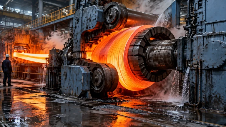
Typical reported thermal efficiency for billet reheating furnaces is 40 to 60%. Conventional furnaces without waste heat recovery can perform below 25%, while high-efficiency systems using recuperation and hot charging can reach 70% or above. Reported heat-balance losses vary widely: flue gas about 15 to 68% of input depending on efficiency and recovery; wall and surface losses 2 to 17%; skid cooling 7 to 13%; and door openings up to about 19% in some configurations. [4][5]
Specific energy consumption for reheating is reported at 1.08 to 2.2 GJ/t for cold-charged slabs and 0.335 to 1.23 GJ/t for hot-charged slabs, depending on entry temperature. Hot charging typically cuts fuel by 25 to 40% compared with cold charging. Each 100 K increase in charging temperature is generally worth about 0.08 to 0.12 GJ/t. Scale loss from iron-oxide formation is typically 0.4 to 3% of slab weight, commonly 1 to 2%; modern walking-beam furnaces can achieve around 0.6%, while poorly controlled furnace atmospheres can reach 1.5 to 2.5%.
Energy basis also matters. Natural gas net calorific value is roughly 10% lower than gross calorific value because gross includes latent heat in the water vapour formed during combustion; the NCV-to-GCV ratio is about 0.9. Energy may be purchased on one basis and efficiency reported on the other. A step change in quoted efficiency can therefore reflect an accounting change rather than an engineering improvement.
ISO 13579 sets the furnace-and-associated-equipment boundary. Duct losses, joint leakage and damper bypass can sit outside that accounting while still being paid for in fuel. A furnace can pass an efficiency test and still lose value through its exhaust train. Recuperative preheating of combustion air to about 400°C is commonly associated with fuel savings of roughly 20%, depending on exhaust temperature and fuel; broader published ranges are 5 to 30% for recuperative preheating and 30 to 50% for regenerative burner systems. These gains must be assessed with the stack’s dew-point and cold-end limits in view. [6][7]
The Duct Is a Yield Line Too
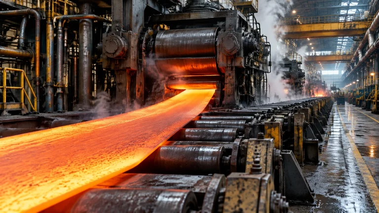
What leaves the furnace travels through the duct: oxide dust, scale carryover and other process residues. Deposits can restrict flow, complicate inspection and add cleaning work. The exact burden depends on the charge, process and exhaust arrangement.
A duct that repeatedly needs cleaning has a maintenance and production consequence, not just a housekeeping issue. Track where deposits accumulate, inspect access points and joints, and account for the outage and cleaning scope in the maintenance plan. A clear duct supports reliable exhaust flow and makes other condition checks more effective.
Where This Lands Across Furnace Applications
The reheat furnace outlet duct and recuperator bypass on a steel rolling mill are one place to map movement and bypass leakage; heat treatment furnaces need sealed, atmosphere-controlled outlet paths because a leak can disturb atmosphere balance as well as efficiency; the fume hood and exhaust path of an aluminum melting furnace must handle salt flux and oxide dust; the joint, damper seal and gasket set belongs in furnace spare parts holding rather than in a project budget; the off-gas path of a melting furnace for steel faces both higher dust load and higher gas temperature; an inspection interval belongs in the asset register for all thermal processing equipment, not only the furnace; flux and preheat fume extraction on a hot dip galvanizing plant can produce aggressive condensate; charge variability in a metal recycling furnace shows up first as duct dust and damper wear; an industrial furnace manufacturer should hand over the as-built drawing and movement budget; industrial furnace systems need a whole-path view from burner flange to stack top; and continuous annealing and tinning exhaust on a wire and cable industry installation must be maintained with the line’s inability to stop for duct repair in mind. Our own equipment packages are supplied with the flue path documented, rather than left to site assembly.
What to Keep on the Shelf
A practical holding policy should match installed sizes and actual failure exposure. Consider keeping:
- A spare fabric joint for each unique size, with insulation stack and temperature rating on its tag, and a spare bellows element for the highest-cycle joint.
- Damper seal and guide sets, high-temperature gasket sheet and ceramic-fibre blanket.
- A calibrated ultrasonic thickness gauge with step-wedge reference block, plus a written baseline by stack elevation.
- A thermal imaging camera with a saved baseline image set.
- A portable flue-gas analyser with a probe long enough to reach the duct, plus a spare filter and probe thermocouple.
- A bolt-torque record and joint bolt set.
- A current as-built flue-path drawing showing every joint, damper, test port and dimensioned movement budget.
Continental Furnaces provides furnace spares and accessories to support reliability and minimise downtime. The cheapest item on that list is the as-built drawing, and it is the one that is always missing.
From Assumption to Evidence: A Five Phase Flue Path Programme
Phase 1, Map: Build the as-built flue-path drawing. Tag every joint, damper, expansion element, test port and support. Record each joint’s movement budget and design temperature against its nameplate.
Phase 2, Measure: At steady load, run an oxygen traverse upstream and downstream of each suspect duct section. Image every joint and the duct shell with a thermal camera, take ultrasonic thickness readings at the stack cold end, and test damper leakage with the furnace at a known load.
Phase 3, Repair and Re-set: Correct anchors and guides. Replace joints whose cycle life is consumed or whose insulation stack is degraded. Remove any shipping straps left in service, re-torque to specification and seal only leaks proved by the traverse.

Phase 4, Verify: Repeat the oxygen traverse and thermal survey. Compare specific energy before and after using the ISO 13579 method and state the boundary. Record the damper leakage figure so the next isolation decision is evidence-based.
Phase 5, Govern: Set inspection intervals with written acceptance criteria, start a joint cycle register, trend stack cold-end thickness and hold the identified spares. Alarm on stack inlet temperature so a heat-recovery change cannot quietly take the stack below its dew point.
Build a Flue Path You Can Defend
Continental Furnaces brings 35+ years of expertise, ISO-certified quality and prompt service to furnace rebuilds and exhaust-path upgrades. We position the flue path as part of the furnace, not an afterthought. Request a quotation and consult with our team to turn undocumented assumptions into a maintainable asset and a route to sustained competitive advantage.
References
- ISO 13579-1:2013, Industrial furnaces and associated processing equipment, method of measuring energy balance and calculating efficiency, general methodology: iso.org
- ISO 13579-2:2013, Reheating furnaces for steel: iso.org
- ISO 13579-3:2013, Batch-type aluminium melting furnaces: iso.org
- Benchmarking study for Thailand’s iron and steel industries, specific energy consumption and heat balance: ctc-n.org
- Bureau of Energy Efficiency, Energy performance assessment of furnaces: beeindia.gov.in
- US Department of Energy, Process heating tip sheet, preheated combustion air: energy.gov
- US Department of Energy, Process heating tip sheet, reduce air infiltration in furnaces: energy.gov
- Combustion efficiency and excess air, natural gas table: Engineering ToolBox
- EJMA, Bellows design and squirm: ejma.org
- Fluid Sealing Association, Fabric expansion joints installation guide: fluidsealing.com
- Guillotine and gas-tight isolation damper engineering data: fouressindia.com
- Cold-end deposition and corrosion control, dew point guidance: watertechnologies.com