Every figure in this article is an indicative benchmark drawn from published conference papers, plant technical reports, supplier technical literature and vendor case studies. Actual values vary with mill configuration and stand count, product mix and gauge, furnace type and zoning, sensor and control vintage, roll and guide condition, and operating and maintenance practice. Use these figures to frame an audit and its design, never as a specification.
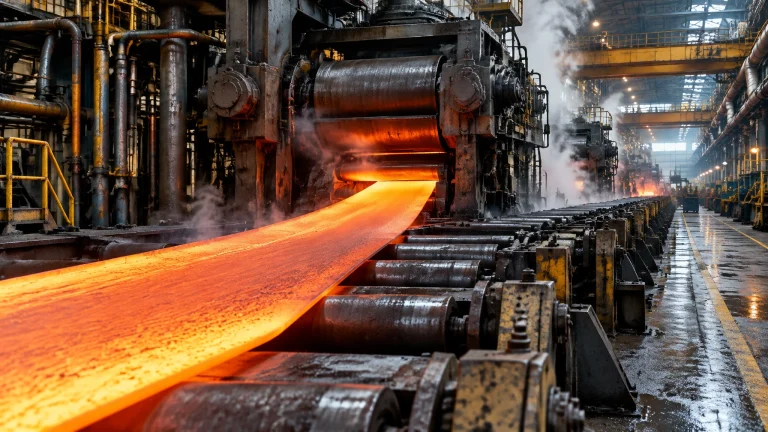
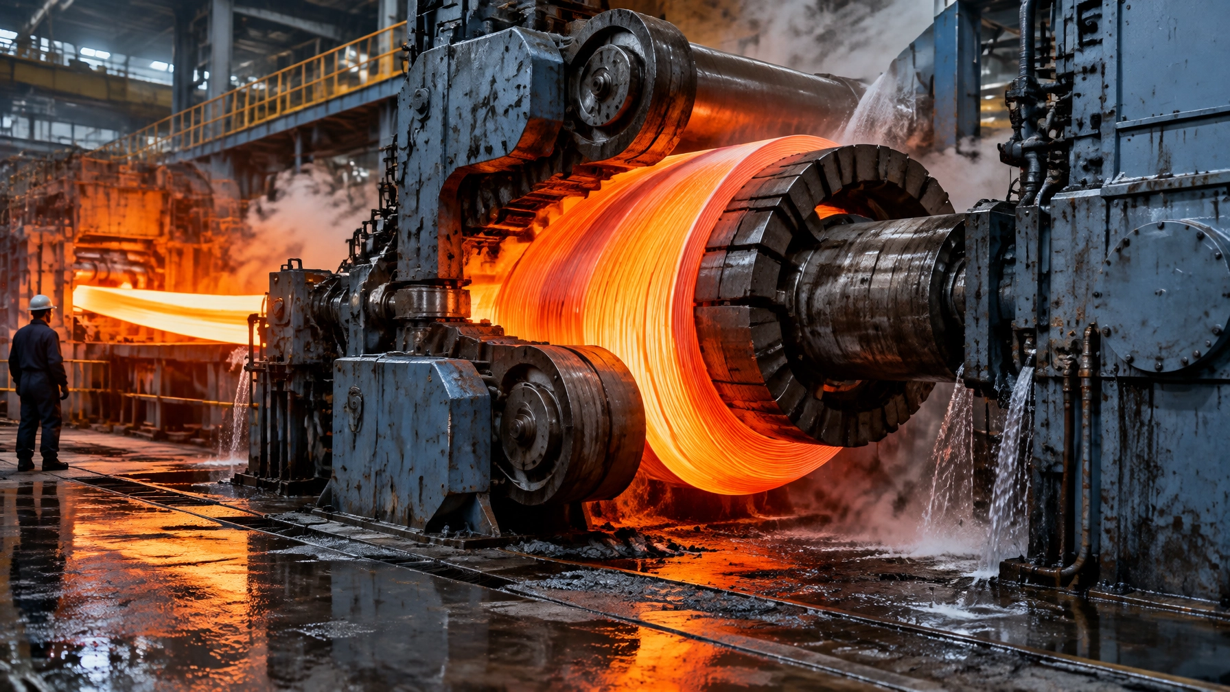
At the exit of the last finishing stand, strip is roughly 800 to 900°C and travelling at up to 100 kilometres per hour. A run-out table more than 100 metres long must bring it to a coiling temperature before the downcoiler winds it. The delivery end has little time to correct upstream variation, but it makes the final decisions about the steel’s cooling history and the coil customers will handle.
In any steel rolling mill, three specifications converge in the final metres: coiling temperature as a metallurgical setpoint, mandrel condition as a mechanical fatigue budget, and coil shape as a logistics tolerance. The downcoiler also performs a repeated expansion and collapse sequence, while run-out table cooling controls how the steel transforms before and after winding.
When these controls drift, the costs spread across departments. Property scatter ships inside coils; shape rejects return to finishing lines for reprocessing; mandrel failures stop production; and cooling water is pumped whether the mill is rolling or not. The visible process deviation and the financial consequence are often recorded in different systems.
A hot strip mill does not ship strip, it ships a coil. The wound steel retains heat and cools over hours, so its temperature at winding influences the microstructure delivered to the customer. Published work on coil slumping and telescopicity also shows how winding tension, inter-wrap friction and handling shape defects can compromise the bore or trigger downstream rework. (Anderssen, Fowkes, Hickson and McGuinness; Ribeiro et al.)
The coiler, then, is not simply a machine at the end of a line. It is a furnace with a mandrel in it, a high-cycle mechanism and a logistics device in the same footprint. This article treats it as a process unit with specifications, tolerances, owners and cost lines.
The coil is the last furnace the steel sees
After finishing, strip can be as thin as about 1 mm, at 800 to 900°C, and travelling at up to 100 km/h. At Kashima Works, the run-out table is divided into two cooling zones with six and ten banks. Pipe laminar nozzles sit above the pass line, full-cone sprays below it, and the table has more than 300 water nozzles in total. Bank valves switch on and off in cycles often shorter than one second. These details come from the Nippon Steel & Sumitomo Metal Technical Report No. 111, which describes the cooling system and control development at Kashima. (Honda et al.)
The production mix made this control task urgent. When development began in 2000, high-tensile steels were roughly 40 per cent of hot strip mill output at Kashima; that share later rose to about 60 per cent, while product strength also increased. The cooling window narrowed as the tonnage of difficult grades grew.
Dynamic cooling control works in plain terms: the model tracks control points along the strip, predicts the temperature at each point and sets the cooling banks so each point aims at the target coiling temperature. The limitation is physical as much as computational. Valve response delay and the distance between measurement points and cooling banks constrain feedback response. In the transition boiling range, water’s boiling behaviour on the strip changes and temperature falls rapidly. This is precisely where many high-tensile, low-coiling-temperature products operate.
Measuring temperature inside the water is the hard part
A pyrometer viewing through cooling water can report a process disturbance as if it were a steel-temperature change. Water between the instrument and strip absorbs thermal radiation, creating a low reading. Droplets scatter radiation and the output falls sharply. Strong air purging removes droplets but disturbs local cooling, so the reading no longer represents the object temperature.
Kashima’s development answer was the fountain pyrometer, mounted just below the strip pass line between table rollers inside a cooling bank. Its purging water fountain stabilises the optical path. The two types serve different zones:
- FP1: wavelength of 0.83 micrometres or less, range 500 to 1,200°C, response 10 ms, used in cooling zone 1.
- FP2: wavelength around 1.1 micrometres, range 360 to 800°C, response 20 ms, used in cooling zone 2.
At a viewing angle of 75 degrees or more, scattering error was held within roughly 10°C. Against a conventional upper radiation thermometer, excluding local falls where water entered its field of view, mean deviation was 2.0°C with a standard deviation of 2.8°C.
That measurement allows feedforward correction before the strip reaches downstream banks. In one cited coil with a 450°C target, the instrument detected sudden over-cooling of about 30°C downstream of the intermediate measurement. A feedforward step reduced downstream bank flow by about 600 cubic metres per hour, holding measured coiling temperature within ±20°C over the coil length. The length fraction within that band improved by 5.8 per cent for 440 MPa steel, 9.7 per cent for 590 MPa steel and 6.4 per cent averaged across low-coiling-temperature steels. A pyrometer looking through a water curtain is measuring a process, not a temperature.
Why the tolerance is a property tolerance, not a temperature tolerance
Thomas, Speer and Matlock used Gleeble simulations of hot strip mill cooling to demonstrate that the run-out table’s finishing cooling step determines more than an endpoint reading. Coiling temperature acts both as the quench temperature, fixing initial martensite and austenite fractions, and as the initial partitioning temperature, governing carbon partitioning during the wound coil’s slow cooling. (Thomas, Speer and Matlock)
In their 0.19C-1.59Mn-1.63Si steel, intercritically annealed samples coiled between about 448 K and 623 K (175 to 350°C) showed quenched-and-partitioned features: martensite blocks with adjacent austenite pools or films. Ultimate tensile strength was insensitive to coiling temperature below about 498 K (225°C) and above about 623 K (350°C), with a transition between plateaus in the intermediate band. Yield strength rose with coiling temperature, so the yield-to-tensile ratio rose. Uniform elongation peaked at about 623 K (350°C). At the highest coiling temperatures, about 723 to 773 K (450 to 500°C), the samples showed pearlite with very fine interlamellar spacing and grain-boundary carbides. The calculated martensite start temperature of intercritical austenite in this steel was about 644 K (371°C).
The authors’ caution is direct: “Coiling temperature control at low temperatures and variations in the cooling profile as a function of position within the wound coil will influence property uniformity.” Steel near the bore and at the outer wrap does not experience the same cooling history. A single coiler-exit reading is therefore an average of a gradient, not a complete description of the coil’s metallurgical condition.
The coiler decisions that should be specifications
| What the coiler decides | Why it is a specification | How it is measured in practice | What hides a drift |
|---|---|---|---|
| Coiling temperature at the strip centre | it sets the phase transformation and therefore yield, elongation and toughness for the whole coil | one radiation pyrometer at the coiler, or in-zone pyrometers in the last cooling banks | a fouled window, a water film in the sight path, or a single-point reading standing in for a width-wise gradient |
| Cooling path shape, not just the end point | two strips arriving at the same coiling temperature by different cooling histories can have different microstructures | the dynamic cooling model plus intermediate temperature readings | recipes that are never revalidated after a grade change or a valve refurbishment |
| Cooling water flow per bank | it is the actuator, so a drifted valve is a drifted metallurgy | bank on/off status and header pressure, rarely the actual flow per bank | a partially blocked laminar nozzle that reads as open in the log |
| Header tank level and pump condition | it sets valve pressure, so it sets controllability | level indication and pump current | surplus overflowing to the scale pit while the pumps stay at fixed speed |
| Wrapper roll and pinch roll pressure | it decides whether the first wraps are tight or loose | pressure setpoints from the coiler setup model | a leaking cylinder, a worn roll, or a step change in strip thickness |
| Mandrel expansion timing and stroke | it decides whether tension is established on the second wrap or the tenth | expansion pressure and position transducers where fitted | reliance on operator judgement at the head end of every coil |
| Segment face condition | it decides whether the bore comes off round and whether the coil will go onto a customer mandrel | visual inspection during roll changes, or nothing | a segment worn into a step that no one measures until a bore defect appears six weeks later |
Five of the seven rows are instrumented in a modern mill, and all seven are usually trended by nobody. That is the whole argument: a process point without an owner, tolerance and trend is not yet a controlled specification.
The coiling sequence is a chain of setpoints
A coiler is not a single machine state but a sequence, and every step in it is a setpoint that can drift. In the preparation state the upper pinch roll is down, the wrapper rolls are closed around the mandrel, and the gaps are set to the incoming strip thickness. Tension is established after three to five turns, at which point the upper pinch roll is released and switched to zero-current control and the wrapper rolls open, except the first for thick strip. At the tail end the mill and coiler decelerate together, the wrapper rolls close to clamp the outer layers, the pinch rolls clamp, and the drive runs in a generating state so the tail does not deviate and the outer layers do not loosen. Coiling speeds reach 30 m/s, with coils up to 45 tonnes and strip up to 25 mm, according to a supplier technical description of underground coiler practice. (Hani Tech)
The geometry in front of the coiler is a specification in its own right. The distance from the last finishing stand is normally 120 to 150 metres, set to allow the strip to cool below its transformation temperature, with near coilers at 60 to 70 metres for thin strip that cools quickly and far coilers at 180 to 200 metres for thick strip that cools slowly. Most modern lines carry more than three coilers for a reason that any steel rolling mill learns from experience: a coiler fault stops the line, and there is no alternative route for a coil already past the last stand.
Expansion is where the mechanical sequence becomes a metallurgical one. At the No. 2 hot strip mill at Usiminas, started up in 2012, the mandrel waits at a smaller diameter than normal, begins to expand once the second wrap is wound, and continues to expand in stepless increments while the strip is coiled. The vendor states the purpose plainly: coiling tension is established very early in the process without strip slippage, which is the same objective the tension-to-weight ratio measures from the other side. The same installation uses three sets of wrapper rolls with quick-opening control, each able to jump the step created by the strip head end, which reduces the top-end marks pressed into the inner wraps. It also carries fifteen laminar cooling banks in three classes, intensive for fast cooling, normal for regular cooling and fine for temperature control before coiling, with cooling zone length and water flows sized for dual-phase and TRIP grades as well as carbon steels. (Satoh, Hasai and Beddings)
Read together, the sequence, the geometry and the expansion behaviour show why coiler problems are rarely one thing. The wrapper roll that presses too hard marks the inner wraps, the expansion that starts too late leaves the first wraps loose, and the cooling bank that stays closed leaves the second wrap hotter than the tenth.

The mandrel is a wear part counted in cycles
Consider a mill producing 350 coils a day for 330 days a year:
350 coils/day × 330 days/year = 115,500 coils/year.
At two expansion and collapse movements per coil for threading and unloading, the mandrel completes:
115,500 coils × 2 movements/coil = 231,000 expansion and collapse movements/year.
That is on the order of a quarter of a million loaded movements annually. Each coil may weigh 25 to 45 tonnes, with the strip surface above 500°C.
A published failure analysis of a mandrel segment at a Brazilian hot strip mill investigated equipment performance data, visually examined the failure, performed non-destructive testing, compared chemical composition with standards, examined the microstructure, measured microhardness for residual stress and carried out fractography. The conclusion was thermal fatigue. (Alcantara et al.)
Thermal fatigue is not a defect that arrives; it is a budget that is spent. The operating choice is whether to count cycles and inspect to a planned interval, or to wait for the crack.
What a rebuild actually consists of
Danieli Service’s 2020 GJ Steel project in Rayong concerned a mandrel originally designed by another manufacturer. The vendor-reported scope included non-destructive testing and dimensional checks by coordinate measuring machine and laser tracker; segment re-engineering and new spare-part design to restore tolerances; dedicated welding and machining to recover surface damage; and honing the body for finish and low component friction. The work also included a new grease system with protected pipe and flexible routing, hydraulic cylinder refurbishment and testing, replacement of obsolete bearings following a dimensional study with the bearing manufacturer, and final inspection and functional testing witnessed by the client. (Danieli Service, GJ Steel)
At Sahaviriya Steel Industries in Bang Saphan, also in 2020, Danieli replaced a downcoiler reel that had been in service since 1994. The project developed new machine kinematics; the vendor projected reel life at over 1.5 million tonnes. The gearbox was refurbished at the OEM’s Thai workshop while the plant continued normal operation. (Danieli Service, Sahaviriya Steel Industries)
The transferable lessons are practical:
- A mandrel rebuild is a tolerance restoration job, not simply a repair. It restores concentricity, segment-face flatness and free sliding.
- Projected life is quoted in tonnes because tonnage, not calendar time, is the wear unit.
The fatigue detail is a radius, the wear detail is a clearance
Raut and Patil’s 2021 paper is a small design study, not plant evidence. It describes a quill-type uncoiler mandrel shaft that failed while carrying a 25-tonne coil at 200 rpm. The shaft material was EN24, with 600 MPa yield strength and 800 MPa ultimate tensile strength. Their analysis found that bending stress from the cantilevered coil weight exceeded the endurance limit and the Goodman factor of safety was below one. The key geometric detail was the fillet radius at a step: reported endurance limits were 101.82 MPa at 7 mm, 107.73 MPa at 8 mm, 115.67 MPa at 9 mm, 116.63 MPa at 10 mm and 136.08 MPa at 16 mm. The study judged 7 mm inadequate and 10 mm sufficient for a factor of safety above one.
The same study analysed the expansion-and-collapse wedge. It recommended replacing a bronze with cast-alloy-steel liner and base-metal combination with a bronze and alloy-steel combination. The reported deformation reduction was 10 per cent, with a 9 mm liner and 8 mm penetration identified as the best combination. (Raut and Patil)
The engineering reading is concise: the mandrel has a radius where stress concentrates and a clearance where wear accumulates. Neither is visible from the pulpit.
Failure signatures worth recording
| Failure signature | Where it shows first | What it usually points at | What to check before the next coil |
|---|---|---|---|
| Cracks on the segment face or at the segment corner | found during a roll change or at rebuild strip-down | thermal fatigue from the expansion and collapse cycle combined with the hot strip contact | dye penetrant or magnetic particle inspection at a stated interval, not an eyeball |
| A polished or stepped band on the segment face | visible as a bright ring on the mandrel | abrasive wear from strip sliding before tension is established | measure the step and compare against the segment tolerance |
| Coil bore out of round, or a coil that will not go onto the customer mandrel | at the coil car or at the customer | segments not expanding to full diameter, or unequal segment contact | expansion stroke, expansion pressure and segment face flatness at each segment |
| Loose inner wraps, or a head end that slips on the second wrap | at the coil, on the inner lap | expansion late relative to the strip arriving | expansion timing against the strip tracking signal, and the pinch roll gap |
| Telescoping, wraps displaced across the coil face | at the coil car or the inspection station | winding tension too low for the coil mass, or a mismatch between coiler and mill speed | wrapper roll pressure, pinch roll condition, and the tension reference for that gauge |
| Top-end marks on the inner wraps | at the customer's uncoiler | the head end step being pressed into the second wrap | wrapper roll jump or quick-opening control response, and wrapper roll surface condition |
| Vibration or a growing axial float at the mandrel | bearing temperature and vibration route | mandrel bearing condition, or a bent or worn shaft | trending, not a one-off reading |
Only two of these seven signatures are visible without an instrument, and both are visible only when the coiler is open.

Coil shape is a tension-to-weight ratio
Telescoping is a coil-shape defect in which one or more wraps move transversely to the rolling and coiling direction. It can result from several hot strip process parameters. Each customer has an acceptable limit; a coil that exceeds it must be reprocessed in a downstream line before dispatch, adding cost without adding product value. The CST-Arcelor Brasil telescopicity corrector paper describes this customer tolerance and the resulting rework. (Ribeiro et al.)
A wound coil slumps, usually slightly, after the mandrel is removed. That small movement can compromise the cylindrical bore and make mandrel reinsertion at a later process difficult and time-consuming. In extreme cases, the coil collapses. The 2009 industry study group report for BlueScope Steel proposed a dimensionless tension-weight ratio:
R = 2TL / DMg
Here, T is winding tension, L is strip length, D is coil diameter, M is coil mass and g is gravitational acceleration. The useful question is not simply the tension setting, but how winding work compares with coil self-weight, in combination with inter-wrap friction. Too little tension lets wraps act independently and slump under their own weight. Too much tension can produce a different failure: kinking at the inner wraps. The study proposed plotting recorded collapse events in a tension-ratio and friction plane, then identifying the critical patch statistically rather than relying on arguments about tension.
Its indicative physical context included coiling stress around 50 MPa for thin-gauge coils, rising to 100 to 150 MPa during the first wraps; inter-wrap friction coefficients of 0.1 to 0.2; and coil masses of 5 to 20 tonnes. Calculate R from plant coil data and recorded events. It is a framing device, not a universal threshold. (Anderssen, Fowkes, Hickson and McGuinness)
| Coil defect | Mechanism | Is the root metallurgical or mechanical | What it costs when it escapes |
|---|---|---|---|
| Telescoping | wraps sliding transversely because winding tension is low relative to coil mass and friction | mechanical, with a metallurgical accomplice in low coiling temperature and hard wraps | reprocessing in a downstream line before dispatch |
| Loose or soft wraps, soft collapse | insufficient tension in the first wraps, or transformation heat softening the coil after winding | both | a coil that cannot be handled normally, and a customer complaint about the inner laps |
| Bore out of round, tight-bore kinking | excessive winding stress at the inner wraps | mechanical | coils that will not accept a mandrel downstream, or a rejected coil |
| Coil collapse | self-weight buckling where winding tension is far too low for the mass | mechanical | scrap, plus a coil handling incident risk |
| Property scatter within a coil | the cooling path and the position within the wound coil decide the local transformation | metallurgical | yield and elongation scatter that surfaces as a customer forming problem or a mill certificate dispute |
| Coil break or surface marking on the inner wraps | head end step pressed into the second wrap at coiling | mechanical | surface rejection on the outer laps of the next process, and a claim that points back at the coiler |
The right-hand column is where the argument for capital is usually lost: reprocessing and claims are often booked in another department’s cost centre.
Cooling water is a metered process, not a utility
TMEIC describes run-out table pumps feeding a header tank that supplies laminar cooling tubes. A constant tank level maintains pressure at the flow-control valves and supports stable flow. Excess water overflows into the scale-water pit, wasting pumping energy. Its control method uses the coiling-temperature computer’s advance flow calculation, mill setup and piece tracking to set variable-frequency drive speeds on pump motors, stopping or slowing pumps during a roll change. TMEIC reports 5,010 MWh per year in pump energy savings, a 43 per cent reduction. As a check, 5,010 MWh divided by 0.43 implies a baseline of about 11,651 MWh/year; after the reduction, consumption is about 6,641 MWh/year. These are vendor-reported case figures, not a performance guarantee. (TMEIC)
A 2022 preprint from the University of Science and Technology Beijing and Anshan Iron and Steel studied a 1,780 mm hot rolling line. Its high cistern had a process band of about ±200 mm. Water consumption prediction using an online sequential extreme learning machine reported a 2.06 per cent mean absolute percentage error, a 2.82 root mean square error and absolute error within 6 tonnes. Optimised scheduling and pump scheme optimisation reduced shaft power from 370.87 to 320.43 kW. The arithmetic is (370.87 − 320.43) ÷ 370.87 × 100 = 13.6 per cent. Water supply fell from 4,027.64 to 3,603.32 cubic metres, a reduction of (4,027.64 − 3,603.32) ÷ 4,027.64 × 100 = 10.54 per cent. Overflow fell from 394.57 cubic metres to zero, a 100 per cent reduction. Pumps operated above 80 per cent efficiency in 95 per cent of cooling stages; average model solve time was 1.009 seconds. These are preprint results from the reported case, not a universal operating promise. (Wang et al., preprint)
The commercial point is direct: the cooling-water system is the delivery-end equipment that continues to cost during a stoppage, while the setup model already knows the next coil’s demand. That forecast can inform pump scheduling, header control and energy management.
What the coiler costs, and where the money actually is
The coiler is cheap to run and expensive to get wrong, because its output is the unit of sale. Most mills can quote the electricity for a running coiler and cannot readily quote the other cost lines, just as they struggle to assign a total cost to mill downtime.
Shape defects beyond a customer’s tolerance require downstream reprocessing, as the CST paper documents. That makes reprocessing the single most avoidable cost: it consumes line time, handling and schedule capacity without changing the original saleable product into a higher-value one.
The furnace side belongs in this discussion. A slab that reaches the mill late and cold enters the finishing train with a cooler head end. That changes finishing temperature, then the run-out table cooling required, and can push the coiler outside its process window. Thermal uniformity is a plant-wide discipline that starts in the reheat furnace and ends in the coil, supported by an integrated approach to heat treatment furnaces.
| Cost line | What it actually is | How it scales with the event | Whether it recurs without action |
|---|---|---|---|
| Coil reprocessing to correct shape | a downstream line pass, plus handling, plus delay | per defective coil, and rising with coil mass | yes, until tension and cooling practice change |
| Customer claims and downgrades on properties | scatter that leaves the plant inside the specification band on average but outside it locally | per claim, and unmeasured until the customer forms the part | yes, quietly |
| Mandrel rebuild and segment replacement | tolerance restoration, welding, honing, new liners, bearings | per rebuild, in tonnes of coil wound | yes, on a predictable cycle if anyone counts it |
| Unplanned mandrel or wrapper roll failure | a mill stop at the delivery end with no alternative route for the coil | per event, in mill hours | yes, and it will happen at the worst grade |
| Cooling water pumping during stoppages and roll changes | pump energy with no strip to cool | per hour of non-rolling time | yes, every shift |
| Coil handling incidents from collapsed or oval coils | crane and coil car exposure, plus scrap | per event, with a safety exposure that does not appear in the cost | yes |
| Inspection added instead of process control | coil inspection stations, sampling and rework loops | per tonne inspected | yes, and it grows |
The pattern is that the first line is visible, the second is invisible, and the seventh is the one a mill keeps buying.
A four phase roadmap away from operator attention
Phase 1: Count what the coiler already does
Over 30 to 60 days, pull actual against aim coiling temperature, cooling recipe, wrapper roll and pinch roll pressures, mandrel expansion timing where a transducer exists, shape defect codes, coil mass and gauge for every coil. Separately count annual coils per coiler, multiply by expansion and collapse movements, and put the annual cycle number where maintenance and operations can see it. In parallel, take the pump energy meter reading for a non-rolling week.
Fewer than 200 coils with a recorded coiling-temperature trace is a sample, not a baseline.
Phase 2: Fix the instruments before the metallurgy
Over one to two quarters, establish written intervals for pyrometer window condition and purge. Verify header tank level band and test header valve response bank by bank. Measure segment-face wear against tolerance; verify expansion stroke and pressure on each coiler; check wrapper roll cylinder leakage, pinch roll gap and surface; and add mandrel bearings to the vibration route. Report coiling-temperature hitting ratio by grade, width and gauge, not as a mill average.
This is where many mills discover the apparent metallurgy problem was a fouled sight glass and a leaking cylinder.
Phase 3: Turn coiling temperature into a property specification
Over three to six months, build grade-wise coiling-temperature windows from the plant’s own mill-certificate data, rather than treating a handbook value as a plant specification. Revalidate cooling recipes after valve or pump work, retain the full coiling-temperature trace with each coil record, and code shape defects by mechanism so telescoping and collapse are no longer one defect code. Compute the tension-to-weight ratio from the plant’s own collapse history.
A mill-wide average hides exactly the thin, wide and high-strength coils that the coiler struggles to control.
Phase 4: Invest in sequence, not in inspection
Over six to 18 months, consider feedforward from in-zone temperature measurement, variable-speed pump scheduling driven by the setup model, a spare segment set and modular mandrel exchange plan, and engineered liner or radius changes where failure analysis supports them. Only then add edge or top-side vision for coil shape; only then consider a new coiler.
Phase 4 without Phase 3 is buying a solution to an unmeasured problem. Buying coil inspection while cooling valves are drifting pays to find defects the process already knows how to make.
2026 technology and market updates
Coiler maintenance becomes a modular exchange, not a field repair
SMS group introduced an easy-to-maintain downcoiler concept in 2024, built around stationary design and modular construction. Dedicated dismantling devices for assemblies such as wrapper roll cylinders are intended to reduce exchange time. The supplier reports reductions of up to 60 per cent and describes service agreements that include mandrel repair cycles and inventory. This is vendor-reported mechanism and service information, not a guarantee of a particular plant’s maintenance result. (SMS group)
The Danieli projects above show the same logic from the other direction: rebuild work is planned in tonnes and performed in a workshop while the plant keeps rolling. The market signal is that OEMs increasingly frame coiler service around intervals, tonnage and inventory. A mill without its own cycle count is negotiating blind.
Coil shape inspection moves onto the line, with a caveat
A 2026 Journal of Intelligent Manufacturing paper proposes an edge-IoT-enabled in-situ vision inspection system for real-time steel coil shape anomaly detection. The full text was not available for this review, so the claim is a research direction, not a validated result here. (Journal of Intelligent Manufacturing, 2026)
The useful change is moving shape judgement from a person at the coil car or a customer downstream to a measurement on the line. The caveat is equally important: a shape measurement identifies which coil to hold; it does not identify a leaking wrapper roll cylinder. Pair the inspection result with process data or the system becomes another inspection station.

Cooling control moves from a better model to more measurement points
The Nippon Steel & Sumitomo approach is conceptually where 2026 investment should focus: improvement came from measuring temperature inside the water rather than simply refining the heat-transfer model. The paper also states the limit plainly: when strip temperature enters the transition boiling range, water’s boiling behaviour changes and control becomes difficult.
For an existing mill, the investment question is where the next pyrometer belongs and whether existing instruments are looking through water. Pattern control also reduced scatter in the temperature history to the rapid-cooling endpoint and in intermediate air-cooling time, bringing coiling temperature closer to target along the coil. That is a microstructure claim, not just a temperature claim.
Mandrel materials are engineered, but the cycle is not
The literature offers levers in liner and base-metal combinations, fillet radii, case hardening, weld overlay and honing. These are real design tools, but a change that removes a stress concentration at a step does not remove thermal cycling that initiates a crack. Material and detail design buy life at the margin; inspection and cycle counting buy notice.
Before a coiler or mandrel investment, ask three questions:
- Is expansion timing and pressure recorded per coil?
- Is segment-face wear measured against a tolerance?
- Is each coil’s coiling-temperature trace retained with its coil record?
What this means across your furnace and mill fleet
The delivery end connects thermal processing to logistics and customer quality, so the same discipline applies across a furnace and mill fleet. A setpoint becomes a specification only when it is measured where the work happens, connected to the product record and owned through maintenance and operations.
- In a steel rolling mill, the delivery end is the last process step and the first one a customer judges.
- In heat treatment furnaces, the coil leaving the mill becomes the charge entering the furnace, making coiling temperature the upstream half of a heat-treatment specification; a quench press or handling transfer is the same specification problem on a shorter clock.
- In an aluminum melting furnace, charging and skimming sequence interruptions change metal temperature and metal loss, just as coiler interruptions change coil temperature.
- In a melting furnace for steel, tapping rhythm and charge mix determine what arrives at the mill.
- Thermal processing equipment includes reheat, quench and mill-side cooling systems, all governed by the same principle: a setpoint is only real if measured where the work happens.
- A hot dip galvanizing plant faces temperature, coating weight and adherence risks during line threading and strip accumulation; a coil that will not unwind becomes the same failure one process later. Related line solutions include the hot dip galvanizing plant and pickling plants, where strip condition and coil handling remain connected.
- A metal recycling furnace receives variable charge, so recovery procedures must cover a wider range of conditions. This connects directly with melting furnaces and recycling projects.
- In the wire and cable industry, rod breakdown and drawing-line breaks are the equivalent delivery-end event; rod-mill coil shape determines whether the pay-off runs.
- Furnace spare parts are the consumable set that determines how quickly a delivery end returns to service, from segment sets and liners to wrapper roll cylinders and pyrometers. Availability is a spares strategy, supported by furnace spares and accessories.
- An industrial furnace manufacturer must connect furnace design, cooling philosophy, coiling specification and spare strategy.
- Industrial furnace systems work best when that connected chain is engineered as one package rather than four separate purchase orders.
An enduring partnership in thermal engineering
A delivery-end review is not a product pitch. It is a practical way to establish where process control, maintenance planning and capital investment will produce the strongest lifecycle value. Continental Furnaces can support a review that includes:
- A coiling-temperature audit comparing aim against actual by grade, gauge and width, with traces to prove it.
- A cooling recipe and valve-response check.
- A mandrel cycle count, segment wear measurement and rebuild plan sized in tonnes.
- A coil-shape review using the plant’s own defect codes and a tension-to-weight ratio computed from its own coils.
- A spare-parts and consumables review sized to the rebuild interval.
- A review of what should be measured before anything is automated.
Continental Furnaces brings 35+ years of thermal engineering experience, ISO-certified quality, solutions customised to the plant’s product mix and duty cycle, and prompt service designed to keep downtime to a minimum. The review can consider heat treatment furnaces, melting furnaces and recycling projects and furnace spares and accessories as connected parts of a plant-wide thermal strategy.
Arrange a delivery-end discussion through our request for a quote page. A mill that can state its coiling-temperature hitting ratio by product, its mandrel cycle count and its coil-shape reject rate by mechanism has already fixed most of the delivery end; a mill that cannot is discovering the cost one coil at a time.
Technical references
- Honda, Nakagawa, Tachibana, Uematsu, Buei and Sakagami, Temperature Measurement Technology in Water Cooling Process and High Accuracy Cooling Control Technology for High Tensile Hot Rolled Strip, Nippon Steel & Sumitomo Metal Technical Report No. 111, March 2016: https://www.nipponsteel.com/en/tech/report/nssmc/pdf/111-04.pdf
- Thomas, Speer and Matlock, Quenched and Partitioned Microstructures Produced via Gleeble Simulations of Hot-Strip Mill Cooling Practices, Metallurgical and Materials Transactions A, 42A, 2011: http://wpfiles.mines.edu/wp-content/uploads/aspprc/ResearchMaterials/Publications/497-Thomas.pdf
- Anderssen, Fowkes, Hickson and McGuinness, Analysis of coil slumping, Mathematics in Industry Study Group 2009 report for BlueScope Steel: https://miis.maths.ox.ac.uk/275/1/bluescope2misg2009.pdf
- Ribeiro et al., Telescopicity corrector: technological innovation at CST-Arcelor Brasil hot strip mill, ABM 43rd Rolling Seminar, 2006: https://abmproceedings.com.br/en/article/corretor-de-telescopicidade-inovao-tecnolgica-no-ltq-da-cst-arcelor-brasil
- Alcantara, Dafe, Cota and Godefroid, Failure analysis of a mandrel segment used in a hot strip mill, ABM 63rd Annual Congress, 2008: https://abmproceedings.com.br/pt-br/article/anlise-de-falha-em-um-segmento-de-mandril-de-bobinadeira-de-laminador-de-tiras-a-quente
- Danieli Service, Downcoiler mandrel revamping for GJ Steel hot-strip mill, 8 October 2020: https://www.danieli.com/en/news-media/news/downcoiler-mandrel-revamping-gj-steel-hot-strip-mill_37_580.htm
- Danieli Service, New concept for HSM downcoiler mandrel replacement, 29 June 2020: https://www.danieli.com/en/news-media/news/new-concept-hsm-downcoiler-mandrel-replacement_37_548.htm
- SMS group, New easy-to-maintain concept for downcoilers, 2024: https://www.sms-group.com/insights/all-insights/new-easy-to-maintain-concept-for-downcoilers
- Raut and Patil, Optimization of the Response of Critical Components of Mandrel, International Journal of Engineering Research and Applications, 11(6), 2021: https://www.ijera.com/papers/vol11no6/Series-3/H1106034754.pdf
- Satoh, Hasai and Beddings, Superior Mill Performance: Advanced Hot Strip Mill, Primetals Technologies Metals Magazine, 2016: https://www.primetals.com/en/metals-magazine/superior-mill-performance-advanced-hot-strip-mill/
- Hani Tech, Equipment Configuration and Coiling Process of Hot-Rolled Strip Coilers: https://hanrm.com/equipment-configuration-and-coiling-process-of-hot-rolled-strip-coilers/
- TMEIC, Cooling Water Flow Control on a Hot Strip Mill: https://tmeic.com/wp-content/uploads/2025/05/Water_Cooling_Flow_Control_on_Hot_Strip_Mill-2_1311947143.pdf
- Wang, Song, Liu, He and Zhao, Energy-saving optimal scheduling of laminar cooling water supply pumping stations in hot rolling mills considering complex intermittent working conditions, preprint, 2022: https://pdfs.semanticscholar.org/d4dc/60559a5674330e92c2c9fd0851c2b6e4f365.pdf
- Development of an edge-IoT-enabled in-situ vision inspection system for real-time steel coil shape anomaly detection, Journal of Intelligent Manufacturing, 2026: https://doi.org/10.1007/s10845-026-02989-y