Caveat: All figures in this article are indicative benchmarks drawn from published conference papers, plant technical reports and supplier technical literature. Actual results vary with mill type and configuration, product mix and section size, line speed and entry temperature, descaler position and header geometry, pump and accumulator sizing, water quality and filtration, nozzle type and condition, and inspection and maintenance practice.
A rolling mill can log pump pressure to a decimal point, then discover the scale defect at the coiler. Descaling is the only system in the mill whose whole output is judged by something that standard instrumentation does not measure: the impact pressure of the water jet at the strip surface.
The setpoint operators quote is main-header pressure. The variable that actually removes scale is impact pressure at the surface. Flow, pressure and the square of nozzle standoff distance determine that impact, so the two readings are only loosely related once the nozzles have been in service. Wear can increase flow while reducing pressure. A displaced header can increase standoff without changing the pump gauge. A misaligned nozzle can move the spray footprint and leave a stripe.
Descaling should therefore be managed as a metered process with a controlled variable, a wear model and an audit trail, not as a high-pressure water utility. That change in perspective brings surface quality, yield, temperature retention and pump reliability into one operating framework.
What descaling is doing, and why pressure is the wrong number
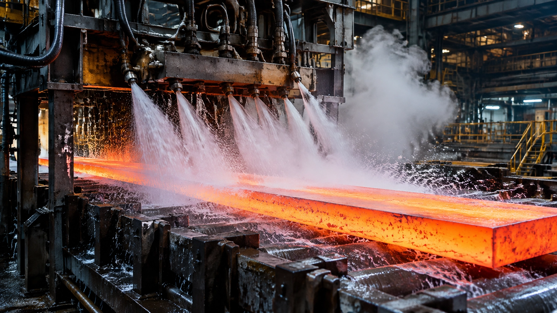
Hydraulic descaling acts on a layered, cracked and often strongly adherent oxide scale. Three accepted removal mechanisms explain why pump pressure alone cannot describe the process:
- Mechanical hammering: droplets strike the scale and deliver local force.
- Shear forces: an angled jet applies force along the surface and helps detach scale.
- Localised failure: high-pressure water enters defects and cracks in the scale, contributing to local failure and separation.
All three mechanisms depend on conditions where the jet meets the steel. Wada, Oshimi and Ueda derived an empirical relation for impact pressure in their experimental units:
p = 5.64 V P / H²
Here, V is nozzle flow rate, P is water pressure and H is nozzle-to-steel standoff distance. The equation captures a critical operating fact: standoff enters as a square. If the header is 20% too high, impact falls to roughly 69% of its former value, a reduction of about one-third, while the pump gauge can show exactly the same pressure as before. 2
Flow matters just as much. Flow divided by area determines jet velocity. As a nozzle orifice wears wider, it passes more water. In a system supplied by a positive-displacement pump, the increased total demand can pull pressure down. The result is a softer jet, even though the worn nozzle is consuming more water.
| Parameter | How it enters the impact equation | How it drifts in service | What you would actually measure |
|---|---|---|---|
| Water pressure P | First power, set by pump and accumulator | Drifts down as nozzle orifices open and as accumulator precharge is lost | Pressure at the header under operating flow, compared with the healthy baseline |
| Nozzle flow V | First power | Rises with orifice erosion and wear | Individual nozzle flow against a new-nozzle baseline |
| Standoff distance H | Squared | Drifts through header distortion, slab impact, weld-base misalignment and thermal growth | Physical survey with a gauge or laser at standstill |
| Spray angle and lead angle | Changes coverage and where the jet lands | Drifts through cracked carbide inserts, heat damage and mis-set tips | Spray-pattern test and angle check |
| Overlap between adjacent jets | Determines whether the strip is covered at all | Drifts as spray width changes with wear and as bases move | Spray pattern on a plate and impact-distribution mapping |

A pump-pressure transmitter remains necessary, but it cannot substitute for direct evidence of impact distribution. A credible control strategy combines pressure and flow readings with nozzle condition, measured geometry, valve response and periodic assessment of the strip itself.
The minimum impact pressure is a materials number, not a preference
Reported minimum impact thresholds depend on scale type. Hennig and Zwanzig, as cited in Japanese technical literature, report values of approximately 200 to 250 kPa to remove primary furnace scale and 50 to 80 kPa for secondary scale. These are useful orders of magnitude, not a universal operating specification for every steel grade and nozzle configuration.
Everloy’s laboratory scale-removal test provides a second reference point. The test used polished spring-steel SUP-6 samples measuring 100 by 200 by 8 mm. Samples were heated to 1,100°C, held for 80 minutes, then moved at 1.3 m/s beneath the jet. The researchers assessed scale removal by image analysis. Stable removal occurred at a maximum impact force of about 0.4 N/mm², corresponding to roughly 90% average removal. Below 0.35 N/mm², average removal fell to around 60%. 10
The figures are consistent in order of magnitude, but they should not be treated as interchangeable acceptance criteria. Scale thickness, adhesion, steel chemistry, nozzle geometry and the exact test method all matter. More important, both sets of findings are commonly far below the impact levels operators believe their systems deliver. That gap is a reason to measure, not a reason to assume.
Ojiako and colleagues at Missouri S&T, working with Steel Dynamics and Spraying Systems, examined the effect of nozzle lead angle. Their controlled study reheated low-alloy steel to 1,065°C, then used flat-fan and rotary turbo nozzles at 0°, 15° and 25° lead angles. Residual scale was assessed using scanning electron microscopy. For the flat nozzle, the best result came at 15°, with a 49 mm pass width and surface roughness of Ra 5 μm. At 25°, the surface roughness was higher at Ra 9 μm. The rotary nozzle was less sensitive to lead angle and performed best at zero degrees in the study. 6
The researchers identify 10 to 15 μm as a critical residual scale thickness range. They also report that more than 5% of hot-rolled metal is internally recycled due to residual oxide scale. The lesson is direct: the strip surface is the only honest impact gauge. A mill that has never cut a representative sample and examined residual scale under a microscope does not know its own minimum.
| Scale at the header | Minimum impact pressure reported | What remains when you run below it | First place to look |
|---|---|---|---|
| Primary furnace scale after the reheat furnace | 200 to 250 kPa | Thick stratified scale left on the slab and pushed into the surface in the first pass | Header standoff and nozzle flow |
| Secondary scale at the roughing stands | 50 to 80 kPa | Adherent patches that reappear within seconds as the surface re-oxidises | Valve response and interstand timing |
| Tertiary scale at the finishing scale breaker | Highest of the three in practice | Thin, tenacious bands and streaks | Spray angle, lead angle and overlap |
| Edges and profile sections | Highest local requirement because the jet strikes at an angle | Edge seams and profile-corner defects | Nozzle arrangement and number of nozzles |
Nozzle wear is invisible, and it fails in the direction nobody expects
Orifice erosion is a quiet process change. The bore widens, flow rises and system pressure can fall. The mill then uses more water to deliver less impact. Because the change is gradual, an operator comparing only the pump gauge with yesterday’s reading can miss the loss.
A widely used operating rule is to replace a nozzle when its measured flow rises 10% or more above the new-nozzle baseline. Visual inspection of the tip detects very little at this stage. Flow testing, by contrast, measures the behaviour that matters. 11
Other failures also change the jet:
- Cracked carbide inserts distort the spray pattern.
- Clogging caused by inadequate filtration reduces or reshapes flow.
- Heat damage affects nozzle bodies and inserts.
- Corrosion around the orifice changes the exit geometry.
- External wear occurs when a top-header spray strikes the opposing nozzle or retainer nut, especially when opposing headers are closely spaced.
The header deserves the same attention as the nozzle. Pipe-wall erosion, misaligned weld bases, slab impact, careless maintenance and damaged threads or welds all change operating condition. A base misaligned by only a few degrees can move the footprint enough to create a gap or excessive overlap. Frick’s audit work identifies poor alignment and overlapping spray defects among the conditions that can generate unscaled stripes. 1
Supplier field guidance also describes replacement headers supplied by a third party in carbon steel instead of the original stainless specification. The replacement pipes had a smaller diameter than the original design, with more than 20 misaligned weld bases per header. Ultrasonic thickness testing found the pipe wall was still sound, so the headers were refurbished rather than scrapped. That is a useful maintenance distinction: a header may be geometrically poor but structurally serviceable, or structurally unsafe despite appearing acceptable from the outside. 12
| Reading | Method | Baseline or pass criterion | What a drift means |
|---|---|---|---|
| Individual nozzle flow | Collect and time a measured volume at a set pressure, or use a calibrated flow cup | Compare with the new-nozzle figure; a rise of 10% or more means the orifice has opened and the jet is softer | Orifice erosion or a flow restriction elsewhere in the test setup |
| Spray angle and pattern | Spray onto a plate or use the supplier’s pattern gauge | Compare with the new-nozzle footprint | A narrowed fan or heavy centre suggests wear or a damaged insert |
| Standoff height and alignment | Physical survey with gauge or laser at standstill | Compare with the as-built drawing, corrected for documented changes | A change moves impact by the square and is a frequent undocumented drift |
| Header wall thickness | Ultrasonic testing on the pressure boundary | Compare with the design minimum wall for working pressure | Thinning is a pressure-boundary and safety issue, not only a performance issue |
| Valve and detector response | Time command-to-full-pressure response from the control system | Establish a repeatable figure when the system is healthy | Slow valve response under-descales the first metres of every strip |
| Overlap and impact distribution | Impact mapping with a force transducer or a painted-plate test | Uniform impact across the full width | Gaps produce stripes; excessive overlap creates a water layer that suppresses impact in the overlap zone |

A useful inspection record is specific to each nozzle and header, not just a generic note that a station was “checked.” It should capture measured flow, spray footprint, physical position and condition, with enough history to distinguish normal wear from a sudden event.
Temperature loss is the hidden bill for over-descaling
Descaling has a thermal cost. Wada, Oshimi and Ueda used an L27 orthogonal-array experiment that varied oxidation temperature at 1,200°C, 1,150°C and 1,100°C, flow at 0.8, 1.5 and 2.3 L/s, pressure at 2.0, 5.9 and 9.8 MPa, and standoff at 20, 24 and 28 cm. Their regression was:
Temperature drop (°C) = 451.7 P V / H² + 9.54
The model had a multiple correlation of about 65%, and the average temperature drop across the trials was 17.1°C. Flow was significant at the 1% level and pressure at the 5% level. The authors calculated that a finishing scale breaker operating at 400 kPa impact could cost about 40°C of surface temperature, compared with about 17°C at 100 kPa. Their conclusion was not to lower impact below the removal requirement, but to increase standoff distance while preserving the required impact. 4
The paper estimates the heat-transfer coefficient under high-pressure descaling at about 18,000 W/m²·K, roughly an order of magnitude above the 1,163 W/m²·K still used in some rolling models. That difference can materially alter predictions of temperature loss and finishing conditions.
The efficiency case is equally clear. At Colakoglu in Turkey, Wenig, Akgul, Savascioglu, Munz and Frick reported converting a conventional hot-strip mill to a newer generation of descaling nozzles. Water use fell by about 20% across all stations, enough to permanently shut down one of three high-pressure pumps. Reported savings were approximately 30,000 kWh per day, or 9,300,000 kWh per year, worth about €642,000 at the time. The report also identified less material cooling and reduced wear on the high-pressure water system as additional benefits. 5
Hnizdil and colleagues compared alternative descaling strategies for heat loss and removal. Two rows spraying in opposite directions with 50 mm between their footprints left 68.5 μm of residual scale, compared with 74.1 μm for two rows spraying in the same direction and 97 μm for a single row. The opposite-direction arrangement also had the lowest heat loss among the tested flat-jet arrangements. 8
The same study challenged a proposed two-pressure arrangement: a 20 bar row ahead of the high-pressure row, intended to crack scale through undercooling. Simulation showed that the low-pressure spray cooled only a thin skin of an insulating oxide layer and did not create an interfacial crack. The concept was not taken to trial.
The hydromechanical rotary descaler installed on Mannstaedt’s blooming line used solid-stream nozzles and delivered comparable or better removal at equal or lower pressure, with about 50% less water and more than 50% less heat loss. A camera assessed the material after descaling, and parameters could be adjusted manually or through an OPC interface. This is a notable example of using measurement to balance removal against thermal cost.
| Configuration or change | Effect on removal | Effect on water and heat loss | Where it fits |
|---|---|---|---|
| Single row at design pressure | Baseline, highest residual scale in the AISTech comparison at 97 μm | Highest heat loss | Reference case only |
| Two rows in the same direction | Improves on single row, 74.1 μm residual | More water and heat loss than one row | Wide strip where coverage is the binding constraint |
| Two rows spraying in opposite directions at 50 mm footprint separation | Best removal of the flat-jet options at 68.5 μm | Lowest heat loss of those options | Retrofit where header space permits |
| In-line nozzle configuration with zero offset angle | Removes the washout area and gives uniform residual scale | Lower heat transfer coefficient in the overlap zone, less heat loss and a flatter temperature profile | New headers or rebuild; tested in a Steckel mill |
| Hydromechanical rotary descaling with solid-stream nozzles | Higher than 90% removal at 150 bar in reported tests | Water consumption down about 50%; heat loss down more than 50% | Blooming and profile lines, especially where water cost dominates |
| Shot blasting | Comparable removal only below 0.3 m/s plate speed | Negligible heat loss | Not a hot-line solution at production speed |
The table describes particular tests and configurations, not a guarantee of plant performance. Actual design selection requires comparison against the mill’s material, speed, geometry and surface criteria.
The pump station is a reliability asset with a consumable bill
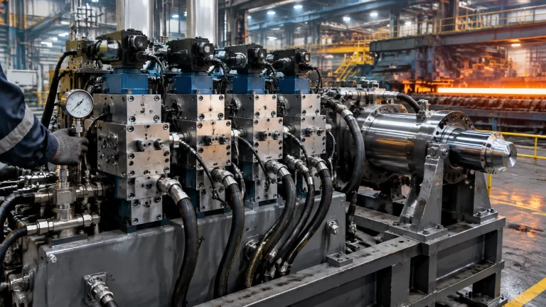
At the pump station, pressure must be treated as the result of a hydraulic duty, not a number to be pursued in isolation. Plunger pumps commonly serve descaling duties in the 150 to 420 bar range. Triplex and quintuplex designs typically run at 100 to 300 rpm, with reported mechanical and volumetric efficiencies in the range of 85 to 92%. Their fluid ends are separated from the power end so abrasive water does not contact the crank mechanism. Supplier guidance offers useful planning ranges, but the actual service interval depends on water quality, operating conditions and maintenance practice. 15
A quick hydraulic-power estimate is:
kW = bar × litres per minute / 600
For 800 L/min at 300 bar, the hydraulic power is approximately 400 kW. Allowing for efficiency and drive losses calls for a motor in the neighbourhood of 450 to 475 kW. This estimate is a sizing check, not a substitute for a full pump and drive specification.
Indicative maintenance guidance for high-utilisation descaling service includes:
- Packing life commonly around 500 to 2,000 operating hours.
- Check-valve inspection on a quarterly basis.
- Fluid-end overhaul around 15,000 to 25,000 operating hours.
- Crankcase oil changes every 2,000 to 4,000 hours.
- Filtration in the region of 80 to 100 microns.
These figures must be reconciled with the selected pump supplier’s requirements and site experience. For hot-mill water above 35°C, inadequate net positive suction head (NPSH) is a primary cause of fluid-end damage. It should be investigated as a root cause, not treated as routine wear.
A triplex pump running at 300 rpm generates 900 pressure pulses per minute. Accumulators and pulsation dampeners are part of the pressure guarantee, not optional accessories. A bladder that has lost precharge can leave the pump-house gauge looking healthy while spray force sags when the header opens. The system may reach a headline pressure but fail to stabilise quickly enough at the strip.
| Component | Failure mode | Typical interval reported | Signature before failure |
|---|---|---|---|
| Plunger packing | Abrasive wear and extrusion | 500 to 2,000 hours | Rising drip rate at the stuffing box and falling volumetric efficiency |
| Check valves | Erosion of ball and seat | Quarterly inspection | Pressure hunting, lost flow and reverse-flow damage |
| Plungers and coatings | Scoring, pitting and corrosion of ceramic or tungsten-carbide surface | Inspect every planned window | Accelerating seal wear and growth of leak paths |
| Accumulator and pulsation dampener | Bladder or precharge loss | Continuous monitoring | Spray-force sag when header opens, piping vibration, hammering and fatigue cracking |
| High-pressure piping, headers and weld bases | Internal erosion, external impact and fatigue at welds | Ultrasonic survey; hydrostatic test at 1.5 times working pressure during major outages | Thinning below design minimum wall |
| Nozzles | Orifice erosion, insert cracking and clogging | Flow test against new baseline | 10% flow rise and narrowed spray fan |
The audit is the cheapest thing you will ever buy
Frick’s audit method starts from a fact familiar to maintenance teams: documented drawings often do not describe the plant as it exists. Modifications are made over years and the records are not always revised. A meaningful audit therefore begins with a physical survey at standstill, not with an assumption that the drawing is right. 1
The site survey should record:
- Measured nozzle positions, pitches and spray heights for every header.
- Nozzle alignment and actual nozzle type.
- Maximum available flow and pressure at every descaling position.
- Filtration condition and header pipe dimensions.
- Feed-pipe locations and counts.
- Evidence of water hammer or unstable pressure.
- Product dimensions, operating speeds and relevant surface-defect history.
Off-site analysis then compares measured flow and pressure with the pump curve, evaluates header and pipe losses, and checks whether accumulator capacity or system restrictions limit the duty. If a nozzle type has no dependable impact data, representative samples can be tested on an impact bench.
A particularly instructive example comes from the TKS Bochum wide hot-strip mill. Between 1992 and 1999, roughing and finishing descaling systems were modernised without changing water pressure or total system flow. Changes to nozzle type and vertical spray height increased impact by approximately 35% at the roughing descaler and 60% ahead of the finishing mill. Downgrading of hot strip for rolled-in scale fell by a total of 55%. That result is a practical demonstration of the value of geometry and nozzle selection, rather than pressure escalation alone. 1
Quality systems support the same argument from another direction. The 2019 ABM paper on rolled-in-scale index improvement at ArcelorMittal Tubarão describes a programme to reduce the occurrence and severity of scale while maintaining a productivity focus. It reflects the need to connect surface-defect data with process conditions, rather than treating defects as isolated inspection findings. 14
An audit is inexpensive relative to a single surface claim on an automotive or API coil. More fundamentally, it is the only way to expose a defect mechanism the plant has not yet recognised.
2026 technology and market updates
Descaling pressures have climbed, and the energy case now argues the other way
Header pressures have moved into the 18 to 22 MPa range and beyond for some specialty, stainless and silicon grades. Pump capacity follows pressure, making descaling one of the larger single electrical loads in hot rolling. But pressure escalation is not the only path to better surface quality.
A 2024 ABM paper from Frick, Wolff and Stein describes the SCALEMASTER ECO+ nozzle generation and its focus on reducing energy consumption and CO₂ while improving surface quality. The work addresses nozzle arrangements that affect washout and offset-angle behaviour, not simply the headline pressure. 13
Variable-frequency drives and hydraulic couplings on pump drives can allow pressure and flow to follow the rolling schedule rather than running flat out through a light campaign. The trade-off is operational: a VFD changes the pressure-flow relationship operators have learned. Without a measured impact baseline, the plant cannot tell whether an apparent energy saving came from more efficient descaling or from taking useful force away from the strip.
Offset angle and in-line headers move from research to specification
The conventional arrangement rotates adjacent nozzles by an offset angle of about 15°, preventing jets from colliding before they reach the surface. Research by Pohanka, Kotrbacek, Resl and Bellerova identified a cost of this convention. Deflected water from one jet pushes into its neighbour and creates a washout area where residual scale measures 12 to 28 μm, compared with 3 to 10 μm in the normal area. 7
An in-line arrangement with a zero offset produced no washout area and more uniform residual scale in the reported work. Peak impact in the overlap zone was twice that of a single nozzle, while the heat-transfer coefficient there was lower and narrower. A new header type was built with SIGMA DIZ and tested at Liberty Ostrava’s Steckel mill, where the plant decided to replace the standard units. 3
The counter-intuitive point is worth emphasising: with a conventional layout, the most descaled area can be the overlap itself. The defect is the washout beside it, where interacting water reduces effective impact.
Rotary solid-stream descaling reaches long-product and profile mills
The Mannstaedt installation described in AISTech 2025 used two rotary descalers on a blooming line, one lateral and one vertical. Pressure, spray distance and rotation speed could be adjusted manually or automatically through an OPC interface, guided by camera detection after descaling. The product mix included hot-rolled profiles with widely varying scale adhesion. Reported results were comparable or better at equal or lower pressure, with about 50% less water and more than 50% less heat loss. 8
Solid-stream nozzles matter because they concentrate local impact with less water and are less sensitive to standoff than flat fans. That is valuable where product height changes throughout a campaign. This approach is currently among the closest examples of closed-loop descaling, but its camera sees the outcome after the fact. It can correct the next bloom, not the bloom that has just passed.
Descaling data becomes coil-level evidence
The emerging data model records more than header pressure. A coil-level record can include:
- Valve-open latency to full impact pressure.
- Header-end pressure differential as a potential clogging signature.
- Cumulative water volume through each header as a wear index.
- Accumulator precharge and cycle data.
- Surface-inspection defect maps tied to the relevant header and operating condition.
Vendor benchmarking has claimed that a majority of mills lack real-time diagnostics on interstand finishing descalers and cannot identify a single clogged nozzle before it contributes to a reject. Some vendor surveys also identify valve-opening delays as a measurable share of head-end scale rejects. Treat such survey figures as directional, not as independently verified universal statistics. 18
Modelling adds a useful layer. Kermanpur and colleagues at Isfahan University of Technology and Mobarakeh Steel developed an artificial-neural-network model using hot-strip-mill data to predict spray impact, width and depth, and calculate overlap for a nozzle arrangement. Their sensitivity analysis identified spray angle, followed by inclination angle, as the most influential parameters. That is a useful corrective to the familiar fixation on pressure alone. 9
The limit remains clear: a pump-house pressure transmitter cannot see a worn nozzle, and no model can repair a header whose bases are misaligned.

What this means across your furnace and mill fleet
Descaling belongs to a connected thermal process. The surface outcome depends on conditions upstream, at the header and through the product’s next stages. The same discipline of measuring flow, geometry, distribution and wear applies across a broader manufacturing fleet.
- A steel rolling mill uses descaling as the interface between reheat furnace and mill. Furnace atmosphere and residence time set the scale load that the descaler must remove. A steel rolling mill that changes furnace oxidation conditions without informing the descaling team is optimising only half the process.
- heat treatment furnaces also depend on nozzle condition, filtration and pump discipline in spray-cooling and quench arrangements. Impact distribution governs cooling uniformity and distortion; a worn nozzle can become a hardness-scatter problem rather than a visible surface defect. See heat treatment furnaces.
- An aluminum melting furnace and a melting furnace for steel shape the incoming melt condition and inclusion burden that affect downstream processing. A melting furnace for steel operating with poor bath control can add oxide challenges to the first passes. Continental Furnaces’ melting furnaces and recycling projects serve these applications.
- A metal recycling furnace handles variable charge mixes, so residual and tramp elements can change scale adhesion from coil to coil. A single descaling setpoint is unlikely to suit a variable mix; measured outcomes and product-specific operating windows are more defensible.
- A hot dip galvanizing plant relies on line drives and pretreatment sprays that need sound nozzle and filtration practice. A clogged pretreatment nozzle can produce coating defects that initially resemble a chemistry issue. Explore the hot dip galvanizing plant.
- In pickling plants, residual scale that escapes upstream descaling remains a downstream surface burden. Spray and nozzle condition are still important process controls, and the same inspection discipline used for descaling can help distinguish a distribution problem from a process problem. See pickling plants.
- The wire and cable industry depends on clean rod surfaces because residual scale can contribute to die wear and surface cracking during drawing. The rod-mill descaler is where much of that surface-quality risk is first controlled.
- furnace spare parts should include the descaling system’s consumables: nozzles, inserts, packing, check valves, seals, filter elements and accumulator bladders. These need condition-based tracking and a wear model, not just a reorder point. Review the furnace spares and accessories.
- Descale headers, spray cooling and quench systems are forms of industrial furnace systems and thermal processing equipment in the strict sense: they manage heat transfer and material condition through controlled water application. An industrial furnace manufacturer that understands reheat-furnace oxidation behaviour is well placed to consider the downstream scale load too.
- Specify industrial furnace systems as a connected process chain, with documented impact, filtration condition and inspection records rather than isolated equipment packages.
A four phase roadmap to descaling you can defend
Phase 1: Baseline and audit, 30 to 60 days
Build a reliable picture of the installed system before selecting changes.
- Record every header’s position, nozzle type, count and pitch.
- Physically measure standoff and alignment on each header.
- Measure individual nozzle flow against a new-nozzle baseline.
- Compare pump curves with measured operating flow and pressure.
- Record filtration condition and water source.
- Confirm whether any impact measurement has ever been made.
- Sort the previous two years of surface claims by defect type and header position.
Phase 2: Restore the measurement, 1 to 2 quarters
Establish repeatable checks that can distinguish design limitations from wear and drift.
- Set up a calibrated nozzle flow bench or a disciplined in-situ flow test.
- Repeat standoff and alignment surveys at a fixed interval.
- Measure header wall thickness ultrasonically on a defined schedule.
- Log valve response timing.
- Cut and examine samples for residual scale thickness at each descaling position. The objective is to establish the mill’s own minimum impact requirement, rather than relying only on a textbook threshold.
Phase 3: Instrument and schedule, 3 to 6 months
Connect process condition with output and make deterioration visible before it becomes a claim.
- Record flow and pressure per header.
- Log valve latency to full pressure.
- Monitor accumulator precharge.
- Use a wear model to replace calendar-only nozzle changes with condition-based replacement.
- Tie each descaling record to the coil and surface-inspection map so a defect can be traced to a header within minutes.
Phase 4: Design and capital, 6 to 18 months
Invest where evidence shows the constraint lies.
- Modify header geometry and nozzle arrangement where the audit identifies layout as the limit.
- Consider in-line configurations where the washout effect has been demonstrated.
- Evaluate rotary solid-stream descalers where product height varies widely or water cost dominates.
- Size pumps and accumulators against measured duty.
- Upgrade filtration where it is limiting nozzle reliability.
- Require documented impact, filtration and inspection data as part of equipment acceptance.
Sequencing matters. Phase 1 cannot be skipped because every later decision depends on knowing the actual baseline. Phase 4 is only safe after Phases 1 to 3 establish which element is limiting performance. Without that sequence, a capital project can raise pressure while leaving the real defect mechanism untouched.
An enduring partnership in thermal engineering
Continental Furnaces brings 35+ years of expertise, ISO-certified quality, customised solutions and prompt service to thermal-processing projects. The descaling argument connects naturally to our portfolio: reheat and heat treatment furnaces whose oxidation behaviour sets the scale load; melting furnaces and recycling projects; galvanizing and pickling lines; and a furnace spare parts and accessories range that supports the consumable discipline a descaling system needs.
Treat a discussion with Continental Furnaces as a descaling and thermal process review, and a strategic step toward sustained competitive advantage. Request a consultation to review the process chain, existing measurements and opportunities for improved control.
A mill that can state its impact pressure, standoff and nozzle wear by header is managing surface quality. A mill that cannot is buying coils back from its customers.
Technical references
- Frick, Audits of Existing Hydro Mechanical Descaling Systems in Hot Rolling Mills as a Method to Enhance Product Quality: https://www.lechler.com/fileadmin/media/fachberichte/metallurgy/lechler_fachbericht_entzundern_audits-of-existing-hydro-mechanical-descaling-systems-in-hot-rolling-mills-as-a-method-to-enhance-product-quality_jfrick_en.pdf
- Schurmann, Measurement and Mathematical Approximation of the Impact of Descaling Nozzles: https://www.lechler.com/fileadmin/media/fachberichte/metallurgy/lechler_fachbericht_entzundern_measurement-of-mathematical-approximation-of-the-impact-of-descaling-nozzles_sschuermann_en.pdf
- Frick, Optimisation of Nozzle Arrangements on Descaling Headers: https://www.lechler.com/fileadmin/media/fachberichte/metallurgy/lechler_fachbericht_entzundern_optimization-of-nozzle-arrangements-on-descaling-headers_jfrick_en.pdf
- Wada, Oshimi and Ueda, Temperature Drop of Steel by Hydraulic Descaling for a Hot Strip Rolling Mill: https://www.jstage.jst.go.jp/article/tetsutohagane1955/77/9/77_9_1458/_article
- Wenig, Akgul, Savascioglu, Munz and Frick, Energy Saving and Process Optimization in a Conventional Hot Strip Mill by Application of the Latest High-efficient Descaling Technology: https://link.springer.com/article/10.1007/s00501-018-0718-8
- Ojiako, Athavale, Osei, Tayebali, Sasso, Buchely, Bartlett, Lekakh and O'Malley, Effect of Water Jet Nozzle Lead Angle on Descaling Efficiency: https://www.spray.com/-/media/dam/industrial/usa/technical-documentation/51111-225.pdf
- Pohanka, Kotrbacek, Resl and Bellerova, Optimal Hydraulic Descaling: https://www.confer.cz/metal/2020/download/3452-optimal-hydraulic-descaling.pdf
- Hnizdil, Pohanka, Kominek, Wunde, Schulze Schencking and Uijtdebroeks, Innovative Descaling Strategies and Their Influence on Heat Losses: https://www.aist.org/getmedia/317ea35a-bb9c-4dbf-9ad4-3afb64351217/020.pdf
- Kermanpur, Ebnonnasir, Key Yeganeh and Izadi, Artificial Neural Network Modeling of High Pressure Descaling Operation in Hot Strip Rolling of Steels: https://www.jstage.jst.go.jp/article/isijinternational/48/7/48_7_963/_article
- Everloy, Evaluation of Scale Removing: https://www.everloy-spray-nozzles.com/en/technology/num-497/
- Spraying Systems, Detecting Nozzle Wear: https://www.spray.com/resources/spraying-basics/spray-optimization/detecting-nozzle-wear
- Lechler, Why Descale Header Maintenance Matters More Than You Think: https://www.lechlerusa.com/en/resources/nozzle-insights/descale-header-maintenance-matters
- Frick, Wolff and Stein, Improved Energy Efficiency and Surface Quality in High Pressure Descaling in Hot Rolling: https://abmproceedings.com.br/en/article/improved-energy-efficiency-and-surface-quality-in-high-pressure-descaling-in-hot-rolling
- Rego, Salles, Possatti and Mendes, Improvement in Rolled in Scale Index on High Productive Mills: https://abmproceedings.com.br/en/article/improvement-in-rolled-in-scale-index-on-high-productive-mills
- BBP Pump, Plunger Pump Application for Steel Mill Descaling: The Complete Industry Guide: https://bbppump.com/plunger-pump-application-for-steel-mill-descaling-the-complete-industry-guide/
- PressureJet, Hot Steel Descaling Systems: How to Specify One: https://www.pressurejet.com/blog/detail/hot-steel-descaling-systems-how-to-specify-one
- Shanghai Metallurgy Equipment Group, Development Trend of High Pressure Descaling Technology: https://www.sme-group.com/blog/development-trend-of-high-pressure-descaling-technology
- iFactory, Descaling and Surface Quality System Analytics: https://ifactoryapp.com/industries/steel-plant/descaling-surface-quality-system-analytics-steel