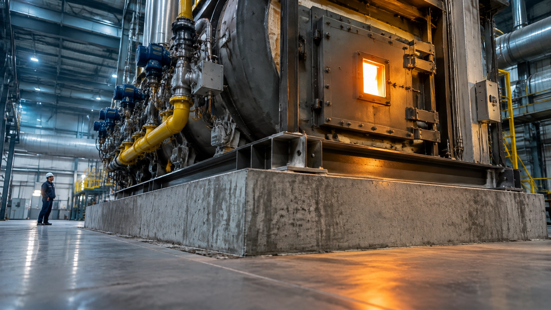
A furnace specification can devote dozens of pages to refractory grades, burner turndown, control philosophy and emissions, then leave the foundation to one line: “suitable foundation by others”. That is where two halves of a project stop talking. The thermal engineer controls shell temperatures; the civil engineer carries the loads. Yet the temperature, movement and level at the interface between them often have no clear owner.
The foundation is the furnace’s coldest component and one of its most thermally abused. It is simultaneously a load path, heat sink, level datum, vibration reference and corrosion environment. Unlike a refractory lining, it cannot be replaced in a planned relining outage. A foundation that runs hot, settles unevenly or restrains thermal movement can transfer those problems into the shell, refractory and operating process.
This article is about the civil and structural interface below and around the furnace. Earlier coverage in this series dealt with refractory selection, refractory installation, refractory dry-out curves, thermal movement arithmetic and expansion joints; those subjects are deliberately not repeated here. The point of this article is what carries and contains all of that.
The figures quoted are a reading of published codes, standards and manufacturer literature; they are given to structure the thinking and are not a substitute for the OEM instructions, the structural design of record, the authority having jurisdiction or a site-specific engineering review.
Suitable Foundation by Others Is Not an Engineering Instruction
“Suitable foundation by others” does not define a safe, operable interface. It leaves five essential decisions unresolved:
- The temperature the foundation is permitted to see during steady operation, start-up and shutdown.
- The movement the interface must permit as steel, grout and concrete expand at different rates.
- The level the foundation must hold, and the datum from which that level is measured.
- The loads it must carry, including thermal and dynamic loads, not only static equipment weight.
- The owner responsible for designing, detailing, installing and checking each part of the interface.
If these are not agreed before construction, problems migrate between disciplines. The furnace supplier may assume the concrete remains cool. The civil designer may assume the thermal barrier is included with the furnace. The installer may then grout the baseplate with the product routinely used on a different kind of machine.
The answer is an interface specification that names temperatures, movements, levels, load cases and accountable parties. That is not added paperwork for its own sake. It protects availability, yield and the long-term profitability of the plant.
The Heat Goes Somewhere, and the Concrete Is Where
Fourier’s law describes one-dimensional conductive heat flow:
q = k × A × ΔT / L
Here, q is heat transfer, k is thermal conductivity, A is area, ΔT is the temperature difference and L is the thickness of the material. Normal concrete has a thermal conductivity of about 1.4 to 1.7 W/mK. Insulating firebrick is about 0.15 to 0.20 W/mK, roughly 7 to 11 times lower. By refractory standards, concrete is a conductor. Concrete in a thermal path is not a support alone; it is a heat leak.[9][10]
Consider a simplified 300 mm section with a temperature difference of 300°C. At a conductivity of 1.6 W/mK, the heat flow through concrete is about 1,600 W/m². At 0.18 W/mK, insulating firebrick passes about 180 W/m². Across a 40 m² hearth footprint, that is roughly 64 kW continuously through concrete, compared with roughly 7 kW through insulating firebrick. At 6,000 operating hours a year, the concrete path represents about 384 MWh a year of fuel spent heating the ground.
This is a one-dimensional steady-state illustration. It ignores contact resistance, air gaps, radiation and the real multi-layer build-up. Its purpose is to show the order of magnitude of an uninsulated path, not to predict a specific furnace or its actual fuel consumption. The practical lesson is that the bottom insulation and its interfaces deserve a thermal budget, just as the hot face does.
A hot baseplate on a cold foundation is a heat exchanger with no control on it, and the grout pad is the fluid in the middle. If no one specifies the permitted baseplate and concrete temperatures, the heat flow is left to the materials and geometry to determine.
What the Concrete Is Actually Being Asked to Survive
Concrete is not immune to the temperature history of the equipment it supports. Published fire-research data for high-strength concrete reports compressive strength reductions of roughly 20% at 100°C, around 25% over the 100°C to 400°C band, roughly 55% at 600°C and around 80% at 800°C. The modulus of elasticity falls to about half by 400°C. Chemically bound water begins to dehydrate well before these higher temperatures, while marked strength decline and microcracking become significant from about 300°C.[5]
These are published material-behaviour trends used as a design principle, not predictions for a particular foundation. They show why a foundation temperature limit must be established rather than assumed. A common furnace-construction objective is to keep concrete beneath the hearth below roughly 300°C, using graded bottom insulation and, in some designs, steel beams supporting the bottom over a ventilated air gap.
High-strength concrete, especially mixes with silica fume or very low water-to-cement ratios, is more susceptible to explosive spalling under thermal exposure. Low permeability limits the escape of moisture, allowing pore pressure to build rapidly. The mechanism is familiar in dense castable refractory: a foundation and a lining can fail in the same way for the same reason.
Design responses include:
- Graded bottom insulation to reduce the temperature reaching the concrete.
- A thermal break or sliding plane detailed for the actual load and movement.
- Reduced concrete exposure, achieved by keeping the hot face farther from the foundation.
- Steel beam support with a designed and ventilated air gap, where the furnace design calls for it.
An air gap can insulate effectively, but it can also allow the underside of the hearth to run hotter. It must be designed and ventilated as part of the thermal system, not merely left open beneath the equipment.

The Grout Pad Is the Smallest Decision and the Most Often Wrong
Grout is a small part of the installation, but it carries load between the baseplate and foundation and experiences the temperature and movement of both. A product chosen because it is standard practice for a pump or turbine may be inappropriate below a hot furnace. Epoxy grout performs well in suitable service, but sustained warmth can reduce its properties and increase creep.
Published grouting literature indicates that cementitious grout is suitable for thermal exposure up to about 400°F (205°C) without significant impact on load-deformation properties. Standard epoxy grouts generally begin to lose physical properties and creep more at service temperatures above about 120 to 170°F (50 to 77°C). Some specialised epoxies are rated to about 300°F (150°C), but with significant reductions in strength and stiffness. These ranges vary by product; the manufacturer’s data sheet governs. ACI 351.1R calls for qualification testing when an application sits outside the standard temperature range.[2][4]
Table 1: Grout family selection against service exposure
| Grout family | Practical sustained service exposure | Behaviour under sustained heat | Where it is the right answer | Where it becomes the wrong answer |
|---|---|---|---|---|
| Cementitious grout | Up to about 400°F (205°C), subject to product data | Load-deformation properties are reported as not significantly affected within this range | Hot baseplates where a compatible cementitious product is specified | When the product’s data, installation requirements or actual exposure do not support the service |
| Standard epoxy grout | Physical-property loss and increased creep generally begin above about 120 to 170°F (50 to 77°C) | Can lose stiffness and strength under sustained warmth | Applications within the selected product’s service range where its specified performance is required | Hot baseplates selected only because epoxy is conventional for other machinery |
| High-temperature epoxy grout | Some products rated to about 300°F (150°C) | Rating may involve significant reductions in strength and stiffness | A specifically qualified application where the manufacturer’s data supports the design | When the rating is treated as equivalent to unchanged room-temperature performance |
| Dry pack or no grout with a designed thermal break | Set by the designed assembly and materials; no generic grout rating applies | Performance depends on bearing, movement and thermal-break design | Where the equipment design requires a defined bearing or sliding interface without a conventional grout pad | When used as an informal substitute without engineered load transfer or movement details |
The governing selection measurement is the baseplate temperature in service, not the ambient temperature at the time of grouting. Measure the baseplate on a hot furnace with a contact probe, then select the grout against that measured number with a design margin and manufacturer confirmation. A catalogue rating without a field temperature is not a complete specification.
Anchor Bolts Are Springs and the Grout Must Not Grab Them
Anchor bolts develop clamping force by stretching as they are torqued. They also need to accommodate thermal expansion of the equipment. Published installation guidance therefore calls for isolating part of each bolt from the grout with a sleeve or other non-bonding material.[8]
Where grout binds the bolt, thermal movement and torque-induced stretch are restricted. The resulting stress can crack the foundation. A fully grouted bolt is not stronger; it is stiffer, and stiffness in the wrong place converts movement into stress.
Anchor bolt positional tolerance is typically quoted at ±2 to 5 mm, and bolts must be perpendicular to the baseplate. These are installation checks, not substitutes for a controlled bolt layout, sleeve detail or verification of the intended free movement.
Vertical cracks in epoxy grout pads commonly arise from different thermal expansion behaviour among steel, concrete and epoxy in the same assembly. Repair practice is to chase and clean the crack, then fill it with an elastomeric sealant that allows movement. Re-grouting the same rigid arrangement repeats the cause rather than correcting it.[7]
Twelve Millimetres Is Structural and It Is Also Process
Published machinery foundation guidance cites allowable differential settlement of less than about 0.5 inch, roughly 12 mm. For alignment integrity of connected equipment, API 686 sets tilt limits of about 0.001 in/ft and angular distortion under about 1/500.[4]
Those are useful structural benchmarks. They do not, by themselves, define a furnace’s process tolerance. The same 12 mm can be a process change. A melting furnace controlling metal depth over a threshold, a galvanizing kettle with specified freeboard to the zinc line, or a walking-beam furnace that must be levelled in millimetres experiences settlement through its operating geometry.
A furnace settlement requirement should express what the process actually needs to hold:
- Metal depth margin over a threshold.
- Freeboard to a zinc line.
- Walking-beam or roller level.
- Burner alignment relative to the furnace centreline.
- Door and seal clearances.
A furnace shell is a rigid steel box. As an engineering reasoning point, if differential settlement tilts it, the shell does not accommodate the tilt by bending. Load redistributes onto three corners while the fourth lifts. That changes the load path through the refractory and can open a joint designed to remain closed.
Level is a datum. A datum that is not marked is not a datum. Many plants can find the furnace drawing but cannot find the height at which the furnace was set.

Five Interfaces and Who Owns Each
A practical interface schedule connects the drawing note to a responsible check. The following five boundaries should be assigned before the foundation is poured or the furnace is set.
Table 2: Interface elements, responsibilities and checks
| Interface element | What the specification usually says | What it is actually being asked to do | The failure mode when it is wrong | The check that catches it |
|---|---|---|---|---|
| Hearth and bottom refractory to foundation top | “Suitable foundation by others” | Limit heat flow, support the hearth and accommodate the specified build-up | Concrete overheating, cracking or loss of support | Review the layer schedule and record foundation-face temperatures in operation |
| Baseplate to foundation grout pad | “Grout in accordance with standard practice” | Transfer bearing loads while tolerating the actual service temperature and interface movement | Creep, debonding, cracking or uneven bearing | Measure hot baseplate temperature and inspect grout contact and cracking |
| Anchor bolts and their sleeves | “Anchor bolts by civil contractor” | Clamp the baseplate while preserving bolt stretch and thermal movement | Restricted bolt movement, cracked grout or concrete, loss of preload | Verify position, perpendicularity, sleeving and nut witness marks |
| Thermal break or sliding plane between shell and foundation | Often not stated | Interrupt heat flow or permit relative movement as required by the design | Uncontrolled conduction, binding and thermal stress | Confirm the installed detail against drawings and inspect the accessible edge |
| Foundation as a mass, a level datum and a vibration reference | “Foundation designed to structural code” | Carry static and thermal load, preserve process level and support dynamic equipment | Differential settlement, alignment change or vibration response | Survey from a fixed datum and check relevant excitation frequencies |
The steel shell, baseplate and concrete expand at different rates. Steel expands at about 12 × 10⁻⁶ per °C and concrete at about 10 × 10⁻⁶ per °C; moreover, the steel is at a temperature the concrete is not. The interface is therefore a sliding joint whether or not anyone has detailed one. The design must determine where movement is allowed and how load remains supported.
A Foundation Is a Thermal Problem Before the Furnace Is Lit
A large foundation begins its thermal history during the concrete pour. ACI 301 gives a default maximum temperature differential of about 35°F (20°C) between the core and surface of mass concrete to control thermal cracking. ACI 207 permits a performance-based thermal control plan to justify other limits.[1][6]
The heat of hydration arrives before process heat, but the governing issue is the same: temperature gradients create differential expansion and stress. A foundation can acquire cracks or damage before the furnace is commissioned if the pour is not managed for its mass and thermal conditions. The thermal-control plan for construction and the thermal-control plan for operation should be written by the same person, or at minimum read and reconciled by both responsible teams.
Which Foundation Problems You Can Actually See
Interface diagnosis begins with a repeatable walkdown, not a demolition scope. Record observations against the as-built drawing and a marked level datum. Look for:
- Vertical cracks in the grout pad.
- Rust staining along the baseplate edge where there is no external water source.
- A baseplate that is not sitting flat.
- Witness marks on anchor nuts that have moved.
- Spalling or a chalky surface on the concrete face at a hot corner.
- A shell corner out of plumb against a marked datum.
- A foundation face that is hot on a thermal camera.
Rust staining at a hot furnace’s baseplate edge is often condensation from a cold bridge, not a leak. The stain still matters: it identifies a local temperature and moisture condition that should be compared with the surrounding interface. A thermal-camera route repeated from the same positions makes changes more useful than isolated images.

Where the Vibrating Loads Really Come From
Published machine-foundation practice requires the natural frequency of the foundation and soil system to sit at least 20% away from the excitation frequency. The natural frequency should be below 0.8 times or above 1.2 times the operating frequency. A 25% margin is sometimes recommended for over-tuned foundations.[3]
For a furnace installation, examine the equipment that actually excites the foundation:
- Combustion and flue-gas fans.
- Charging and discharging machines.
- Walking-beam and roller-hearth drives.
- Hydraulic power units.
The furnace shell itself is not the exciter in this assessment. That is why foundations designed only for static furnace weight can be surprised by a fan or auxiliary drive. Dynamic checks must follow the actual operating equipment and its excitation, not simply the main furnace outline.
Foundation Problems Are Paid For in Available Tonnes, Not in Concrete
A refractory failure is an expensive outage. A foundation failure is a different class of event, because the repair has to happen beneath an asset that cannot be moved and a process that is losing money while it waits.
Reason through what an intervention at the base of a furnace actually consumes:
- Production time, because there is no way to lift a furnace to reach its own foundation while it is hot.
- Refractory that was not due for replacement, because reaching the bottom of the hearth means demolishing what sits on it.
- Temporary support design, because the furnace must be carried while the interface beneath it is opened.
- A new survey baseline, because the level the plant has been using stops being a reference the moment the support changes.
- A permanent concession, because the process tolerance expressed in metal depth, freeboard or beam level has usually been renegotiated in the direction of less margin.
Set that against the cost of the controls that prevent it: a temperature budget in the specification, a grout family chosen against a measured hot baseplate temperature, sleeved anchor bolts, a marked datum and a survey repeated at a fixed interval. None of these are large items. The asymmetry is the argument. The foundation is the one component in the furnace whose failure cannot be absorbed inside the maintenance budget or deferred to the next reline.
That is also why the interface belongs in the capital project conversation rather than the maintenance conversation. By the time the furnace is hot, every decision that governs it has already been made.
Where This Lands Across Furnace Applications
The civil interface affects a steel rolling mill as much as it affects heat treatment furnaces, because both depend on level and stable equipment alignment. A melting furnace for steel and an aluminum melting furnace each require their own process-based settlement and thermal limits. The same interface questions apply when specifying thermal processing equipment for a hot dip galvanizing plant or a metal recycling furnace. As an industrial furnace manufacturer, Continental Furnaces considers the support conditions as part of the design conversation for industrial furnace systems serving the wire and cable industry, alongside the planned availability of furnace spare parts.
What to Keep on the Shelf for the Interface
Interface consumables and measurement equipment deserve the same planned availability as other critical maintenance items. Depending on the installed design, maintain:
- Cementitious and epoxy grout in date, with batch records.
- Anchor bolt sleeves and non-bonding tape.
- Stainless shims of graded thickness.
- Thermal-break board or calcium silicate sheet in the installed thickness.
- Crack gauges and monitoring pins.
- Plumb survey targets.
- A fixed and marked level datum.
- A thermal camera with a defined route around the foundation faces.
- The as-built foundation drawing with the datum dimensioned on it.
These are not interchangeable substitutes for a designed repair. Keep the specified product and thickness traceable, and confirm compatibility before use. See furnace spares and accessories for support with operational spares planning.
The cheapest item on this list is the marked datum and it is the one that makes every later measurement comparable.
From Interface to Programme: A Five Phase Foundation Integrity Programme
A disciplined programme turns inspection into an operating control. It assigns a sequence, provides a basis for intervention and prevents the foundation from disappearing between furnace and civil responsibilities.
-
Phase 1: Survey and datum. Mark and record a fixed level datum and plumb targets, survey the shell corners, and record baseplate temperatures on a hot furnace. Keep the readings with the drawing and the date of measurement.
-
Phase 2: Diagnose. Read the tell-tales against the as-built drawing, chase every crack in the grout pad, take the thermal-camera route, and classify each finding as cosmetic, monitor or intervene. Record the basis for each classification so the next survey can test whether conditions changed.
-
Phase 3: Specify. Write the interface specification the original project left out, with a temperature budget for the foundation, a movement allowance, a level tolerance expressed in furnace process units, and a named owner for each of the five interfaces. Link the requirements to the equipment duty and actual operating conditions.
-
Phase 4: Intervene. Repair with the right method: elastomeric treatment for movement cracks, re-grouting only where the grout family was wrong, sleeved and re-torqued bolts, and a thermal break where the path was never broken. Never apply a rigid patch over a moving joint.
-
Phase 5: Govern. Put foundation temperatures and the survey into the same routine inspection as the refractory and shell, and review them at a fixed interval. Carry the datum forward into every rebuild so the next generation of measurements is comparable with this one.
Build an Enduring Reliability Partnership
A foundation interface is a lifecycle issue, not a one-time civil handover. Continental Furnaces brings 35+ years of expertise, ISO-certified quality, customised solutions and prompt service to industrial thermal-processing projects. Our engineers work with customers to connect furnace duty, civil design, installation and inspection into an enduring partnership focused on efficiency, yield, regulatory compliance and sustained availability.
Request a consultation or request a quote to review the foundation interface for a new installation or operating furnace.
Bring the furnace duty, foundation drawings and hot-condition measurements to the discussion, and make the ground beneath the furnace part of your reliability plan.
References
- ACI 301 and ACI 207 guidance on mass concrete temperature differentials and thermal control plans, as summarised in ACI's published FAQ on temperature limits for mass concrete, https://www.concrete.org/frequentlyaskedquestions/faqid/889.aspx
- ACI 351.1R, Report on Grouting between Foundations and Bases for Support of Equipment and Machinery, https://www.concrete.org/Portals/0/Files/PDF/Previews/3511R-12web.pdf
- ACI 351.3R, Report on Foundations for Dynamic Equipment, https://www.concrete.org/Portals/0/Files/PDF/Previews/351.3R-18_preview.pdf
- API RP 686 foundation and grouting practice as presented in an industry tutorial on foundation and grouting systems, https://itwperformancepolymers.com/wp-content/uploads/Foundation-and-Grouting-Systems-Manuscript-TPS-2025.pdf
- V.K.R. Kodur, “Properties of Concrete at Elevated Temperatures,” ISRN Civil Engineering, https://www.hindawi.com/journals/isrn/2014/468510/
- National Ready Mixed Concrete Association, CIP 42, Thermal Cracking of Concrete, https://www.nrmca.org/wp-content/uploads/2021/09/42pr.pdf
- Published technical bulletin on vertical cracks in epoxy grout, https://www.fivestarproducts.com/wp-content/uploads/TB208-Vertical-Cracks-in-Epoxy-Grout-na13471eng-rA-202401.pdf
- Published guidance on anchor bolt installation, sleeving and debonding, https://www.adhesiveservices.com/_files/ugd/a4a5e5_25d1d5cb311d4d7781350bc3e7695665.pdf
- Thermal conductivity of common materials including concrete, https://www.engineeringtoolbox.com/thermal-conductivity-d_429.html
- Insulating firebrick thermal data, https://www.bnzmaterials.com/insulating-firebrick/insulating-firebrick-data-page/