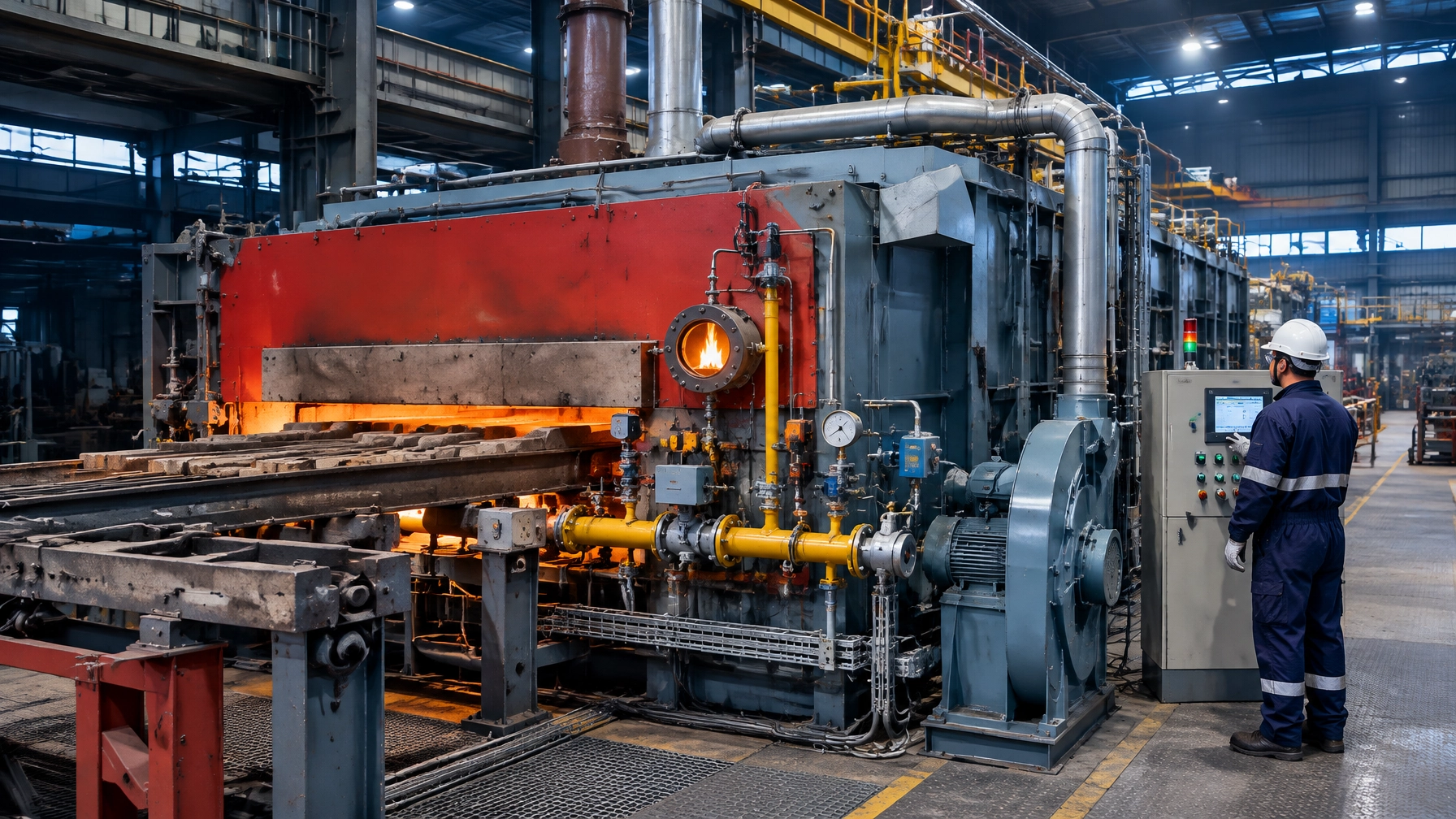
A furnace receives most of its engineering attention in the middle of the cycle, when temperature, atmosphere and production quality are being controlled. Yet much of the damage that shortens its life occurs at the two ends: during light-off and during cooldown.
The start is where the furnace is asked to prove it is healthy. The stop is where it is left in a condition that decides the next start. Both require defined conditions, hold points, evidence and named release authority. A target soaking temperature without a written ramp instruction is only half a procedure.
Plants can mistake speed for competence and constraints for obstacles. In a refractory-lined furnace, removing a restraint to save time may simply transfer the cost to the lining, anchors or shell. Every start and stop is a thermal cycle, and cycles consume campaign life alongside operating hours.
This article differs from earlier posts in the series: it is not about refractory dry-out and the first warm-up curve after lining installation, covered on 4 November; installation methods such as gunning, shotcrete and vibratory casting, covered on 13 November; refractory selection by zone, covered on 8 November; burner management interlocks and proof of closure, covered on 6 November; or instrument air and actuator reliability, covered on 18 November. It addresses the production procedure for every start and stop of a furnace already in service, including restart classification, purge, ramp, hold points, sign-off and the largely undocumented cooling side.
The figures below are a reading of published standards, manufacturer guidance and engineering literature, offered as a benchmark and a starting point. They are not a substitute for the furnace manufacturer instructions, the lining supplier heat-up schedule, the authority having jurisdiction or a site-specific safety review.
The Good Start and the Good Stop Are Different Documents
A start procedure governs the path from a known safe state to stable operation. It needs purge evidence, light-off sequence, ramp rate, hold points and release authority. A stop procedure governs the path from production to a safe, known condition for the next shift or maintenance activity. Combining them on one page commonly leaves the cooling steps vague.
A stop procedure must answer five questions:
- What temperature curve applies, and what conditions require a slower cool?
- What are the required door, damper and exhaust positions?
- Is an atmosphere purge required, and how is it proved?
- How will the plant prevent frost, water ingress or condensation damage?
- Which auxiliaries remain running, for how long and for what purpose?
The operating instruction must distinguish a controlled stop from an emergency stop. Each has different actions, risks and release requirements.
The Furnace Grows 144 mm and the Drawings Assume That It Will
Linear expansion is calculated as coefficient × original length × temperature change. For structural steel, a coefficient of about 12 × 10⁻⁶ per °C means a 12-metre furnace body heated through 1,000°C grows by about 144 mm. That movement is a design condition, not a defect.
If fully restrained, thermal stress is modulus × coefficient × temperature change. With a modulus near 200 GPa, stress builds at about 2.4 MPa per degree Celsius of restrained change. A mild steel member with yield strength around 250 MPa reaches yield after roughly 104 C of unrelieved change. The actual restraint pattern is complex, but the principle is direct: a seized guide, welded slide plate or grouted roller converts movement into stress, which finds the weakest component.
Slides, guides, rollers and expansion joints are load-bearing parts of the movement system. Bellows guide rods and limit rods manage movement; limit rods restrict travel and provide backup restraint against pressure thrust if a main anchor fails. Bellows squirm is a column-type instability in which internal pressure buckles the bellows laterally, reducing cycle life or causing failure. Where installation and operating temperatures differ, the specified pre-compression or pre-extension must be set at installation. Shipping restraints remain in place until the unit is anchored and guided, then are removed as instructed.

The Restart Decision Is a Classification, Not a Judgement Call
Classify the restart from the condition at the moment of starting. A remembered temperature or verbal assurance is not evidence.
Table 1. Restart classes and release evidence
| Restart class | Condition at the moment of start | Purge position | What proves the condition | Who releases it |
|---|---|---|---|---|
| First heat-up after lining work | New or repaired lining requiring its prescribed heat-up | Follow the approved lining and burner procedure | Supplier schedule, instruments and completed hold records | Responsible engineer and operations |
| Cold start with lining at ambient after service | Furnace is cold, lining is dry and the cause of shutdown is understood | Full proved purge before ignition | Temperature readings, airflow proof and timed purge record | Operations under approved procedure |
| Warm restart with chamber below the hot-restart threshold and all burners out | Chamber remains warm but the exemption condition is absent | Full proved purge | Chamber reading and purge completion record | Operations |
| Hot restart with chamber proven above the threshold | Chamber condition is confirmed by the required independent device | Purge may be omitted only where the approved interlock permits it | Independent, calibrated proof and interlock status | Authorised operations role |
| Restart after an unplanned trip with fuel proved off | Trip cause and safe fuel isolation are established | Apply the approved trip-recovery purge logic | Fuel-off proof, trip investigation and airflow/timer evidence as required | Operations and responsible engineer |
Purge Is a Volume and a Timer, Not a Habit
NFPA 86 guidance calls for four system volumes of fresh air or inert gas per volume of total system volume before ignition. The system volume includes the combustion chamber, burner zones, exhaust ductwork, stack and connected heat-recovery equipment. The purge must be timed and proven; if airflow falls below the minimum, the timer must stop. There is no fixed five-minute rule for every furnace. Purge duration depends on system volume divided by proved airflow, so two furnaces of equal rating can require different times.
The hot-restart provision may allow pre-purge omission when the chamber is proven above 760 C through a high-temperature bypass interlock. It may also apply where every burner has safety shutoff valves and at least one burner remains ignited in the same chamber. The temperature exemption is a proven condition, not a remembered one. Its sensing device must be independent, calibrated and incapable of being left bypassed.
In practice, purge proof is defeated by:
- A jammed damper that indicates open.
- A proving switch set so low that a fan coasting down still satisfies it.
- A bypass left in from a previous shift.
The Cold Start Passes Through a Corrosion Window
Flue-gas acid dew point typically falls between 125 to 152 C, depending on sulphur trioxide and water vapour. Corrosion peaks roughly 30 C below the dew point. Operators typically maintain gas temperatures 11 to 17 C above it where the design and process allow.
This creates a real conflict: the lining needs a controlled ramp, while vulnerable flue-path surfaces should not remain cold in the condensation window. The answer is not to ramp faster. Identify which surfaces pass through the window and for how long, then use design-appropriate measures such as low-fire bypass, duct insulation, air-preheater bypass or draining dead legs. The flue-path design decides the solution; not every furnace has a bypass.

The Cooldown Is the Half of the Procedure That Does Not Exist
Published lining schedules commonly use heat-up and cool-down rates of 25 to 100°F per hour, roughly 14 to 56°C per hour. Thick or dense castables commonly require rates at or below about 50°F per hour, roughly 28°C per hour. Staged holds around 300°F, 600°F and 1,000°F, approximately 150°C, 315°C and 540°C, are used to release moisture progressively. Controlled cool-down is commonly capped at 100 to 200°F per hour, approximately 56 to 93°C per hour. These are ranges, not a recipe; the lining supplier schedule governs.
Above 100 C, residual moisture can generate localised high-pressure steam within dense castable. Spalling risk depends on gas-generation rate and material permeability. Low permeability combined with a fast ramp is dangerous. Holds below about 110°C allow water to leave while the structure remains permeable. If a lining has absorbed water during a wet outage or wash-down, treat it as newly wetted and apply the applicable new-lining schedule.
On cooldown, the hot face contracts before the shell. A sudden temperature gradient can cause thermal shock. Opening doors for access at 800°C turns a controlled cool into an uncontrolled one and can drive severe local gradients. A well-designed curve can make the last 300°C take longer than the first 700°C, because the controlled reduction protects the lining and structure as temperatures equalise.
A written cooling instruction should specify:
- Temperature bands, maximum rates and hold conditions.
- Door, damper and exhaust positions at each stage.
- Atmosphere management and required purge evidence.
- Condensation, water ingress and frost precautions.
- Monitoring points, abnormal-condition response and release authority.
Every Cycle Spends Lining Life
The lining, anchors and steel shell expand at different rates. Repeated movement concentrates stress at anchors and the shell interface, leading to surface cracking, spalling, anchor deformation and breakage. Microcracking can deepen with each cycle. Published industrial cycle counts range from about 30 to over 150, depending on materials and anchor design; this is illustrative, not predictive.
A plant with four starts a week consumes its lining four times faster in cycle terms than a plant with one start a week. Campaign life measured only in operating hours ignores a major part of what is consuming it. Put starts and stops into the production plan and the lining campaign budget.
The Idle Versus Shut Down Decision Should Be Calculated Once
The lining stores heat, and replacing that heat after a shutdown takes energy and time. Firebrick specific heat is commonly 700 to 960 joule per kilogram kelvin. Above 1200 C, frequent short-term shutdowns may be more energy-efficient than holding at idle temperature, depending on furnace cooling rate, reheat time and heat lost through walls, floor and roof. Low-thermal-mass ceramic-fibre linings reduce the penalty of cycling. This is an engineering calculation that plants too often make by habit.
Table 2. Operating choice by outage situation
| Situation | Recommended course | The reason | The number that decides it |
|---|---|---|---|
| Next charge within the same shift | Compare low-fire idle with a planned stop | Avoid unnecessary loss of stored heat or fuel at idle | Idle loss versus cooldown and reheat energy |
| Next charge the following morning | Calculate both options for the actual interval | Furnace mass and cooling rate determine the better choice | Hold duration and reheat time |
| Planned weekend or 48-hour outage | Use the approved controlled stop unless a calculation supports holding | Extended idle loss may exceed the restart penalty | Cooling curve and total heat loss |
| Unplanned stop with cause not established | Stabilise in the approved safe state; investigate before restart | A repeat trip can compound equipment and lining damage | Fault evidence and safe restart conditions |
| Stop requiring internal access | Controlled shutdown, isolation and verified safe access | People and equipment must not be exposed to residual heat or hazards | Access temperature and isolation status |
Hold Points and Who Is Allowed to Release Them
A hold point is a signed gate, not a pause in the sequence. Operations releases temperature and rate. Maintenance releases mechanical condition and bypass status. The responsible engineer releases any deviation from the written curve.
A deviation record must capture at least:
- Furnace identification, operating mode, date and time.
- Actual and target temperatures, rate and hold duration.
- Relevant trends, alarms and purge or bypass status.
- Reason for deviation, immediate controls and observed condition.
- Name and signature of the person authorising release.
The control thermocouple reports chamber temperature, not lining hot-face temperature. During a ramp, the hot face is hotter than the reported value. That is why ramp rate, rather than chamber setpoint alone, is the variable to control. A ramp with no recorded deviation is not a controlled ramp; it is an unrecorded one.

Where This Lands Across Furnace Applications
Start and stop discipline changes with the process. In a steel rolling mill, movement clearance and coordinated line restart are central; heat treatment furnaces require disciplined temperature uniformity and product release; an aluminum melting furnace must protect melt quality while controlling burner and holding conditions. A melting furnace for steel prioritises safe hot-metal handling and refractory integrity, while a metal recycling furnace must account for variable charge and contamination risks. The hot dip galvanizing plant and the wire and cable industry depend on stable continuous operation, so restart planning must account for connected line equipment. Across all of them, thermal processing equipment needs evidence-based ramps and a written cooling curve, while an industrial furnace manufacturer must engineer movement, controls and serviceability into industrial furnace systems and hold furnace spare parts that match what was installed rather than what a catalogue happens to list. For process-specific configurations, see our precision heat-treatment solutions and aluminium melting and holding equipment.
Keep the Start and the Stop Stocked
The right critical spares determine whether the next start happens on schedule. Build a start-and-stop-specific list, with installed specifications and replacement lead times. A planned inventory of furnace spares and accessories supports reliability and reduces avoidable downtime.
- High-temperature bypass interlock device and sensing element where the hot-restart exemption is used.
- Purge timer and airflow proving switches.
- Flame detectors, viewing heads and windows; ignition transformers and electrodes.
- Ramp-control thermocouples and resistance thermometers, with the correct type and length of extension cable.
- Shell and dual-depth thermocouples for lining monitoring.
- Expansion-joint bellows in the installed size, with shipping restraints and pre-compression setting recorded.
- Slide plates, guide rollers and anchor studs.
- Door and damper actuator seals and limit switches.
- The consumable items actually used during a start, specified for the installed equipment.
The bypass device is the wrong place to economise: it carries a safety-critical proof function, and its failure can invalidate the restart basis.
From Procedure to Practice: A Five Phase Start and Stop Programme
- Phase 1: Document what you actually do. Shadow two real starts and one real stop. Record what happened, not what should happen.
- Phase 2: Separate the four procedures. Write distinct instructions for start, hot restart, controlled stop and emergency stop, each with hold points and release authority.
- Phase 3: Fix the movement path. Inspect slides, guides, rollers and expansion joints. Verify pre-compression and removal of shipping restraints. Confirm nothing has been welded, grouted or shimmed into rigidity.
- Phase 4: Instrument the holds. Tie temperature instruments, bypass proof, purge proof, shell monitoring and the deviation log together.
- Phase 5: Govern it. Review deviations weekly, count cycles in the production plan and express the lining campaign budget in both cycles and hours.
Build an Enduring Reliability Partnership
A controlled start and stop is a practical investment in safety, lining life, uptime and profitability. Continental Furnaces brings 35+ years of expertise, ISO-certified quality and prompt service to support equipment throughout its operating life. Start a conversation about reviewing the procedures for your specific furnace and request a technical consultation and quotation. The objective is an enduring partnership and sustained competitive advantage.
References
- NFPA 86, Standard for Ovens and Furnaces.
- NFPA 86 pre-purge volume and airflow guidance as summarised by burner and combustion equipment engineering guides, including the Eclipse Combustion Engineering Guide.
- Expansion Joint Manufacturers Association, standards and guidance for metal bellows expansion joints.
- NIST Handbook 124, Energy Management for Furnaces, Kilns and Ovens.
- U.S. Department of Energy process-heating guidance on furnace heat loss and thermal mass.
- Published refractory castable heat-up and cool-down schedules issued by lining manufacturers, including the Resco Products and Plibrico schedules for conventional and low-cement castables.
- Research literature on drying of dense refractory castables and explosive spalling mechanisms, including numerical and experimental drying research.
- Published lining and anchor literature on thermal cycling fatigue and anchor life.
- Published review literature on flue-gas acid dew point and low-temperature corrosion in flue, duct and heat-recovery equipment.