The figures in this article are indicative benchmarks drawn from published conference papers, plant technical reports, supplier technical literature and vendor case studies. They vary with mill configuration and stand count, product mix and gauge, furnace type and zoning, sensor and control vintage, roll and guide condition, and operating and maintenance practice. Each reported figure is attributed in the body; vendor-reported results are labelled as such and should be treated as directional, not guaranteed plant outcomes.
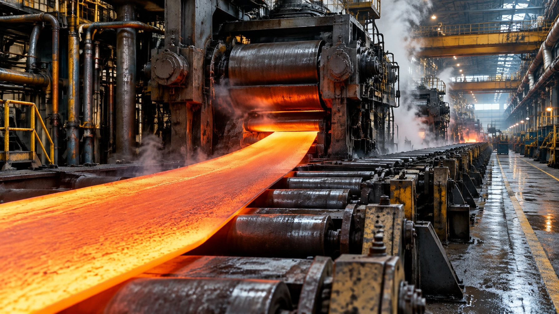
A hot strip mill does not make every metre of a coil under the same conditions. It makes its most vulnerable metres during the transition from an empty finishing train to a stable, tensioned strip. A red-hot transfer bar head end enters F1, then threads through six or seven stands to the downcoiler. Only after the strip is captured and tension is established can the mill accelerate towards its production speed.
That opening interval concentrates several disturbances: the bite loads the stand, speed falls before the control system recovers, the head end is not yet tension-stabilised, and the strip has not yet demonstrated that its temperature, width and shape match the setup assumptions. The window may last only seconds, but the consequences of a failed thread do not. A cobble can destroy the coil, damage rolls and guides, expose crews to hot-strip recovery work, and halt rolling while the reheating furnace continues to manage the slabs waiting behind it.
The engineering case is therefore broader than strip guidance. Threading is a measurable process characteristic, with a cost profile that extends well beyond lost rolling time. It reaches into yield, roll condition, recovery duration, delivery commitments and furnace fuel use.
This edition follows that chain from the first bite to the restart. The practical argument is straightforward: measure the head end, classify cobble signatures, put a clock on recovery and coordinate furnace pacing with mill status before committing to automation.
The two seconds that decide the coil
A typical hot-strip route begins with slabs around 220 to 260 mm thick and 900 to 2,250 mm wide. The IJERT 2026 process paper describes reheating to approximately 1,150 to 1,250°C, roughing to a transfer bar around 20 to 40 mm thick, and finishing through a tandem mill of six or seven stands to final gauges in the region of 1.2 to 25 mm. It gives finishing entry temperatures up to about 1,140°C, exit temperatures around 850 to 940°C, coiling temperatures around 450 to 650°C, and coil weights of the order of 28 to 35 tonnes. These are representative process-envelope values, not a universal operating recipe. The IJERT process paper provides the cited ranges and notes the dependence on product and equipment.
Threading is deliberately performed at a lower speed, commonly around 10 to 12 m/s. Once the head has reached the downcoiler and tension is established, the automation accelerates, often called the zoom, towards top speeds of 20 m/s and above. The acceleration profile has to account for the strip’s temperature history so that finishing and coiling temperature targets remain attainable. The first metres are therefore not a slow version of steady rolling: they are a distinct transient with different load, tension and thermal conditions.
Speed drop and bite loading
When the head end enters a roll gap, the drive is suddenly loaded. Roll speed drops before the regulator recovers, and the disturbance travels through subsequent stands as strip is threaded. The immediate production symptom can be a kink or gauge deviation in the first metres. The engineering issue is that the transient torque demand and speed dip stress the drivetrain and disturb the roll speed at the point where the strip is least able to tolerate an error.
Primetals describes its Speed Drop Expert as model-based feedforward compensation of load torque during threading. The system anticipates the torque requirement and adjusts drive behaviour so the load step is not left entirely to feedback recovery. Primetals’ supplier literature lists minimised speed drops and torque peaks, more consistent roll speed and therefore improved thickness and width consistency from the start of the strip, the possibility of rolling harder material, and retrofit capability for most existing main drives without extensive modification. Those are supplier-described benefits, not a plant-specific performance guarantee. The relevant mechanism is anticipatory compensation, not a promised percentage improvement. Primetals Speed Drop Expert.
Looper response and tension
A looper holds interstand tension while absorbing mass-flow mismatch. It is a mechanical actuator inside a fast process-control problem. The strip can experience a meaningful tension disturbance before the looper has moved far enough to correct it.
Nippon Kokan’s 1986 paper describes two different responses to that constraint. Enlarging loopers to lift heavier sections had degraded tension control for small sections. For larger sections, the company developed full-stand looperless rolling: estimate interstand tension from rolling torque and force using least squares, then trim the upstream stand speed through a PID controller. For small sections, it separately developed optimum looper control using tension meters and a six-state linear model with Riccati feedback.
The published result from the Keihin Works hot-strip finishing mill, where the method was applied in March 1984, was a 40 per cent reduction in longitudinal thickness variation, from 50 to 30 micrometres at 2.3 mm gauge. These are the results reported in the paper, not a present-day universal benchmark. Nippon Kokan’s tension-control paper.
Both speed drop and looper response can look like operator threading problems. In practice, they are often tension and measurement problems. The remedies described in the literature rely on measured state and control action, not on asking an operator to react faster.
The following register connects head-end dependencies with the service findings and first symptoms that can be checked on a real line.
| What the head end depends on | Why it matters at threading | What erodes it in service | First measurable symptom |
|---|---|---|---|
| Roll gap and levelling at each stand | a level error of a fraction of a millimetre is a steering command once the strip is a metre into the gap | roll change and chock wear, uneven thermal crown, calibration drift after a stoppage | one-sided load difference that repeats on the same stand |
| Interstand tension and looper response | tension has to be established within a few hundred milliseconds of bite or the strip buckles | looper inertia, hydraulic or electric actuator lag, worn looper roll and arm bearings | looper angle hunting at the head end |
| Speed schedule and speed drop compensation | the head end must arrive at each stand at the speed the setup model assumed | drive tuning drift, load cell drift, compensation model not updated for the current product mix | first-metre gauge spike and a visible kink |
| Strip temperature at finishing entry | flow stress roughly doubles across the finishing temperature window, so a cold head end rolls like a different steel | furnace skid marks, transfer time, descaling and interstand cooling | head end force higher than the setup prediction |
| Transfer bar width and camber | a narrower or curved head end finds the guide instead of the gap | sizing press and edger setup, width drop at head and tail, roughing roll wear | one-sided edge marking and camber on the transfer bar |
| Guide and side guide condition | guides are the last mechanical barrier before a fold | misalignment, worn liners, loose hold-downs, previous cobble damage | edge rub marks and a guide gap that no longer matches the setup sheet |
| Measurement chain: load cells, pyrometers, width gauge, interstand cameras | every control action above is only as good as its sensor | scale on lenses, water and fume in the field of view, drifting pyrometer emissivity, uncalibrated load cells | operators switching loops to manual and leaving them there |
Six of the seven rows are maintenance findings, not operator findings. A mill that measures threading badly will repeatedly explain its cobbles as operator error, even when a guide, sensor or calibration issue is the real lead indicator.

A cobble is a signature, not bad luck
A cobble is uncontrolled folding, buckling or accumulation of strip following a loss of stability in the roll gap. It may appear as a pinch, fold, twist or wrap around equipment, and it takes the mill down. That definition and the process context are described in the IJERT hot-strip-mill paper. IJERT process paper.
The underlying chain is usually cumulative. Differential elongation across strip width creates waviness, camber or buckling. Rolls and the looper cannot absorb the instability, after which the strip pinches or piles. Temperature, width and gauge are coupled contributors because each changes flow stress and the distribution of elongation.
Thermal variation and head-end width
The IJERT paper discusses reheating-furnace skid marks as a source of cooler width-wise bands, with differences reported up to 60°C. It reports that temperature variation above about 20 to 30°C correlates strongly with flatness defects. It also cites one study in which reducing width-wise temperature variation from 25 to 30°C to 5 to 10°C cut cobble rates by about 48 per cent. That is a single cited study, and the change was achieved through furnace optimisation, descaling and roll-cooling improvements together. It should not be read as a furnace-only effect or as a forecast for a different mill. IJERT process paper.
Thermal uniformity is a plant-wide discipline, from slab heating through transfer and rolling. It is also central to heat-treatment furnace engineering, where temperature distribution and material handling have to be assessed together rather than as isolated settings.
Width at the head end is also not simply a matter of how carefully an operator followed the setup sheet. JFE’s sizing-press research explains how the press and edger create a dog-bone thickness profile. During horizontal rolling, that profile produces a rolling-direction velocity difference between edge and centre at the free head and tail surfaces, causing width shrinkage. The study reports head-end shrinkage just downstream of the roll bite to about 800 mm downstream, and tail-end shrinkage from about 1,200 mm to about 330 mm upstream of the roll centre. In one simulated case, width shrinkage of 45 mm exceeded width spread of 27 mm, making the rolled width narrower than the input. Consequently, the F1 guide must be set for the head end that actually arrives, not only for the nominal transfer-bar width. Goto, Kimura and Miyake, ISIJ International.
The crop shear is another part of the threading envelope. Global Gauge’s crop-shear note states that the front end must be cut squarely to avoid finishing-mill cobbles and steering issues, and that the tail should also be cropped squarely for the next process. The supplier notes that one to two inches of unnecessary scrap per bar becomes significant over a year, which is why vision-based cut-line optimisation can have a yield case as well as a stability case. Global Gauge, Crop Shear Optimization.
Read the evidence, not just the event label
Thickness spikes and wedge amplify load differences between stands. A guide misalignment of even a couple of millimetres can raise cobble risk on thin gauge. Mill incident records also commonly include looper malfunction, roll wear or spalling, sensor inaccuracy, equipment instability and delayed response. Those factors should be investigated as interacting conditions, not isolated causes.
The IJERT paper provides a worked cobble record in which the head end struck the F6 entry centre tong and folded. The report identifies a head-end temperature drop, abnormal finishing-mill setup and guide misalignment in the same event. It compares roll-force, differential roll-force and differential roll-gap traces for F5, F6 and F7 against a good coil. The useful lesson is the co-occurrence of setup, temperature and guide evidence, not a single number extracted from the plots. IJERT cobble record.
A signature register turns that kind of record into a repeatable investigation. The table below is a practical classification framework derived from the cited incident analysis and strip-walking literature, not a set of universal acceptance limits.
| Signature at the mill | Where it shows first | What it usually points at | What to check before the next coil |
|---|---|---|---|
| Head end folds or rises at F1 or F2 entry | head end force and gap trace, stand camera | bite geometry, head end temperature, roll gap level | head end temperature and crop quality, then level |
| Head end strikes the entry guide or a tong | guide and stand camera, impact marks on the guide | guide gap set for the setup sheet rather than the actual width | guide gap against measured head end width |
| Tail-end whip between the last two stands | interstand position measurement or the operator's view | asymmetric roll gap at the upstream stand, wedge in the incoming bar | differential roll force and wedge at the last two stands |
| One edge buckles and cambers the strip | edge rub marks, width gauge at exit | one-sided cooling, uneven roll wear, guide contact | spray pattern symmetry and roll wear profile |
| Centre buckle in thin gauge only | flatness at exit, force trace across the pass | crown mismatch, excessive reduction in the last stands | crown and flatness setup for the gauge being rolled |
| Mill loads and stops without a fold | drive torque and speed trace | tension collapse, drive fault, looper actuator failure | drive diagnostics and looper actuator response |
| The same failure repeats at one width or one grade | cobble register sorted by product | a specific setup model or a specific guide setting | the product-specific part of the setup model |
The signature is what makes a cobble register useful. A register sorted by cause is a rumour; a register sorted by signature is an action list.
What a cobble actually costs
Start with the hourly rate, because every other number is derived from it. Acoem’s vendor case study on an ArcelorMittal hot rolling mill estimates unplanned downtime at EUR 6,400 per hour of lost production. The case says a catastrophic F6 reducer-bearing failure could last four to six days, and that a planned EUR 30,000 bearing replacement avoided an estimated EUR 930,000 in production losses. Acoem reports a 180 per cent rise in acceleration on bearing number four of the F6 reducer, detected in June 2021. This is vendor-reported case-study material and directional, not a benchmark for every mill. Acoem case study.
A cobble-specific example comes from a long-term computer-vision deployment in an Indian bar mill, reported by Kurrey, Pujari and Gupta of IIT Bhilai in an arXiv preprint. The authors report that the mill had faced around 60 cobbles per month, each with about 30 minutes of downtime; their system helped prevent nearly 10 cobbles per month. They also state a production-loss figure of Rs 21 lakh per hour and report savings of about Rs 1.15 crore per month. These are author-reported results from a preprint and should be treated with that context. Kurrey, Pujari and Gupta, arXiv.
The arithmetic is worth doing on the page. Ten avoided events at 30 minutes each is five hours, and five hours at the stated Rs 21 lakh per hour is about Rs 1.05 crore, roughly 91 per cent of the Rs 1.15 crore the authors report. So the saving in their account is almost entirely the stoppage time itself, with the coil, the rolls, the guides and the recovery labour sitting in the remaining few per cent. The ordering is the useful part. It says the funding case for a cobble project rests on mill hours recovered, and that the yield and roll shop arguments are the second argument rather than the first, which is the opposite of how these projects are usually presented. The monthly saving figure is the authors' own, from a preprint, and should be read as an indication of magnitude rather than as a decomposition of cost.
Roll damage is a large and measurable part of that impact. Verma and co-authors at SAIL’s R&D Centre and Bokaro Steel Plant describe hot-mill work rolls exposed to thermal fatigue, fire cracks and surface or subsurface damage from operating deviations and accidents. Their paper states that surface cracks deeper than about 0.2 mm must be found and removed, and reports that NDT-assisted grinding was followed by work-roll spall cases falling by almost 50 per cent, back-up-roll consumption falling 10 to 15 per cent excluding material-related failures, and overall mill delay due to roll changes falling by more than 40 per cent. They report NDT programme cost at less than 20 per cent of the work-roll saving alone. The authors also emphasise full shell and bond-line inspection after a mill wreck with visible roll damage such as dents, welded strip or small half-moon spalls. A cobble is a roll shop event as well as a rolling event. Verma et al., 17th WCNDT.
The furnace is also inside the bill. While the mill is down, the reheating furnace cannot stop instantaneously. Slabs already at temperature must be held, slowed or risked. Holding consumes fuel, increases oxidation exposure and can leave a slab arriving too cold at the head end, the very condition that may have contributed to the original event. This coupling makes furnace pacing part of threading management, not a separate department’s concern.
The following cost structure is a plant-accounting checklist. It is not a published universal price list; quantify each line with the plant’s own rates, weights and recovery history.
| Cost line | What it actually is | How it scales with the event | Whether it recurs without action |
|---|---|---|---|
| Rolling time lost | mill hours not producing, priced at the plant's own rate per hour | with recovery hours, not with the coil | yes, every event |
| Coil and slab yield | the coil scrapped or downgraded, plus the slabs behind it already at temperature | with coil weight and with how far into the sequence the mill was | yes, on the same products |
| Work roll damage | fire cracks, spalling, pinches and weld marks found or missed at the roll shop | with severity and with how quickly the stand is cleared | yes, if grinding practice does not follow |
| Back-up roll and bearing damage | contact stress damage and bearing distress from the shock and from welded strip | with severity, rarely, but expensively | no, if the roll is inspected |
| Guides, looper, descaler and side guides | bent liners, sheared hold-downs, damaged looper roll, blocked nozzles | with the location of the fold | yes, in the same stand |
| Recovery labour and safety exposure | people cutting and pulling hot strip out of a stand under time pressure | with the number of stands involved | yes, and it is the line that hurts people |
| Delivery penalty | late coils, sequence re-planning, customer allocation | with order book tightness | yes, and it is often invisible internally |
Most mills can quote the first line and cannot quote the second to the seventh. That is why cobble projects are sometimes funded as safety or quality projects and then quietly drop off the agenda: the full operational cost has never been brought into the investment case.

Steering is a measurement problem before it is a control problem
An operator cannot see the strip between stands. A manual correction made at the pulpit is therefore often a correction to a symptom that has already travelled two stands downstream. A measurement in the interstand space changes the task from reaction to control.
Nippon Steel’s strip-walking control paper describes a specific failure chain: after leaving a stand, the tail end walks; its edge touches the next stand’s entry-side guide; the edge buckles; and the next stand rolls the fold. The result can be roll damage and an unscheduled roll change. Their interstand sensor uses two high-speed CCD cameras with stereoscopic vision. The report gives raw resolution of 2.5 mm per pixel, edge detection based on maximum differential intensity per scan line, and least-squares regression weighted by that intensity so water droplets and fume degrade the fit rather than simply breaking it. The output interval is 12 ms, edge resolution is below 1 mm, and measured accuracy is 6.4 mm at 2 sigma against a 10 mm requirement. Nippon Steel, Strip Walking Control Technology.
The control is model predictive because strip translates and rotates: the walk seen at the sensor is not necessarily the walk at the stand. Nippon Steel placed the sensor about one third to one half of the interstand distance upstream of the stand being controlled. The published outcome was tail-end trouble incidence reduced to 22 per cent of the previous rate, across strip widths. The conventional load-difference method reached 85 per cent and degraded on wide strip. The paper also notes that the conventional method can act in the wrong direction when incoming wedge, rather than strip walk itself, is the cause.
Global Gauge’s AISTech 2025 presentation describes an interstand centreline deviation system using camera assemblies and lasers crossing the field of view at fixed pixel positions. Its presentation reports millisecond-level response, with measurement fed forward and back to finishing-stand cylinders through a PID loop using upstream and downstream camera inputs. Control begins only after the last n healthy readings, preventing a bad frame from moving a stand. The reported savings are reduced cobbles, bruised rolls from tail whip and side-guide maintenance. Global Gauge also reports pinches reduced by more than 75 per cent and holes and gall reduced by more than 75 per cent in conjunction with improved practices, and identifies bearing-failure prediction as an emerging use of the same feedback. These are vendor-reported outcomes, not independently transferable performance guarantees. Global Gauge, AISTech 2025 presentation.
Primetals’ Hot Mill Steering Expert combines strip-threading control, strip-guidance control and strip-tail-out control. Its supplier literature describes ShapeMon camera systems feeding a model predictive controller that generates work-roll levelling commands to align the head end with the centreline during threading. Guidance control keeps the strip straight behind the finishing mill and is verified by width gauges; tail-out control aims to minimise tail-end pinching. The supplier also describes wedge minimisation through transverse displacement and retrofittability to existing plants. Primetals Hot Mill Steering Expert.
Three suppliers, one conclusion: interstand position measurement at intervals of 10 to 50 ms, feeding an automatic levelling or steering command, is commercially available as a retrofit approach. A mill that relies only on load difference plus an operator’s eye is choosing to run threading open loop.
The table separates what the available functions measure from the defects they cannot compensate for. It is a decision aid, not a vendor comparison or performance promise.
| Function | What it measures or commands | What it actually fixes | What it does not fix |
|---|---|---|---|
| Interstand centreline measurement | strip edge position between stands, tens of times per second | the missing measurement in every manual steering decision | a roll gap that is level but worn |
| Automatic levelling or steering | work roll levelling command from upstream and downstream cameras | head end alignment and tail-end walk | incoming wedge that the model does not know about |
| Tail-out control | strip position as the tail leaves each stand | tail-end pinching and bruised rolls | a guide that is already damaged |
| Speed drop compensation | predicted load torque at bite, fed forward into the drive | first-metre gauge and the torque peak that wears the drivetrain | a drive that is already mis-tuned or a coupling that is already loose |
| Looperless tension estimation | interstand tension from rolling torque and force by least squares | tension control without waiting for a mechanical looper to move | a load cell that has drifted |
| Furnace pacing model | slab temperature and mill interval time, optimised together | slabs arriving too cold or too hot at the head end | a furnace zone that cannot hold setpoint |
The column on the right is the honest one, and it is also the maintenance list. Control cannot repair a damaged guide, a drifting load cell or an unstable zone.
Recovery is a procedure written before the event
Recovery is where a controllable 40-minute event becomes an uncontrolled three-hour one. The decisions are not conceptually difficult, but they must be made early, by people who are simultaneously trying to understand what happened and make the area safe. The furnace decision is often taken last. It should be taken first, because the furnace queue is changing while the mill floor is being cleared.
A recovery plan should assign decision ownership and start the relevant clock at the event, not at the point when the mill is ready to restart. For a known delay, the furnace strategy is to reduce zone setpoints along a calculated curve rather than switch the furnace off. For an unknown delay, hold first and reduce once the slabs are classified as ready. The target is for slabs to reach the discharge door at the right temperature when the mill is ready, not earlier. The IJERT process paper describes discharge temperatures typically in the 1,150 to 1,250°C band and furnace zone operation spanning roughly 900 to 1,380°C depending on zone. These are process-envelope figures from that paper, not prescribed targets for every furnace. IJERT process paper.
Tata Steel’s reheating-furnace work is a strong published example of bringing furnace prediction and mill pacing together. Boeder and Speets describe a first-principles dynamic furnace model incorporating zonal radiation, weighted sum of grey gases, skid radiation and conduction, individual slab cells, and combustion of natural gas, coke oven gas, blast furnace gas and hydrogen blends. The model is linearised at each timestep and discretised with an extended Tustin transformation that can handle non-square state matrices as slabs are charged and discharged within the prediction horizon. Their distributed MPC coordinates four parallel furnaces at IJmuiden with a horizon of at least one furnace load, 35 timesteps and a one-minute sample, using ADMM to agree the shared interval time. Boeder and Speets, Tata Steel, AIST 2025 conference paper.
Their example schedule gives mill interval times around 64 to 80 seconds per slab, with a single 360-second interval representing a delay. Furnace interval times are roughly 275 to 300 seconds once slabs are shared across four furnaces. The paper’s honest conclusion is that distributed control does not make the mill faster: the slowest furnace sets the pace. The benefit is that faster furnaces do not overheat slabs while they wait, reducing energy use and oxidation loss. The prize is not speed. It is not cooking the queue.
The counter-risk is equally important. Restart too quickly after a stoppage and cold-head-end material can reach the first stands. That can produce the second cobble, after the crew has already spent hours clearing the first.
The clock values in this table are a proposed plant recovery template, not source-wide measured benchmarks. They are intended to make ownership and sequence explicit, then be calibrated to the mill’s own recovery records.
| Stage | Clock from the event | Decision that has to be made | What goes wrong if it is improvised |
|---|---|---|---|
| Detect and stop | 0 to 1 minute | where the strip has stopped and whether the mill can be backed off | drives fight the strip and the fold gets worse |
| Isolate and make safe | 1 to 5 minutes | energy isolation, exclusion zone, who is allowed on the floor | people walk into a stand holding stored energy |
| Furnace hold decision | 0 to 15 minutes | hold, slow or risk the queue, and when to start the recovery ramp | slabs arrive too cold and the restart produces a second cobble |
| Clear the stands | 15 to 120 minutes | cut and pull, or roll out, stand by stand | roll damage from cutting in the wrong place |
| Inspect rolls and hardware | concurrent with clearing | grind, change or run, and which stand to inspect first | a cracked roll goes back into service |
| Restart and requalify | 60 to 180 minutes | threading speed, temperature recovery and the first coil | the requalification coil is sold as prime or skipped |
| Review and close out | 24 to 72 hours | cause, signature and the one change to make | the same cobble returns on the same product next month |
A written procedure is not bureaucracy. It is the only way the furnace decision is made by someone who knows the queue, rather than by whoever happens to be nearest the pulpit.
A four phase roadmap from register to automation
Phase 1: Build the register, 30 to 60 days
Collect every cobble and near-miss for at least twelve months, then sort by signature, stand, product, gauge, width, grade, shift and time since roll change. Add the corresponding furnace-delay records, roll-shop findings cross-referenced to incidents, and a recovery-time log measured against actual event times. Build the cost model from Table 3 using the plant’s own rates rather than a benchmark.
The rule is simple: a register with fewer than twenty events is not yet a dataset; it is an anecdote collection. Include near-misses so the plant can see the precursors as well as the failures.
Phase 2: Fix measurement and mechanical basics, 1 to 2 quarters
Before buying a control system, verify the physical and measurement conditions on which it will depend:
- Set guide gaps against measured head-end width, not only the setup sheet.
- Align side guides to a stated plant tolerance.
- Check looper rolls, arms and bearings.
- Calibrate load cells and check pyrometers.
- Clean camera lenses and verify that cooling is working.
- Verify stand levelling and roll-gap zero after every roll change.
- Document a product-specific threading speed schedule.
This is also the point to identify where a manual loop has become the permanent operating mode, and why.
Phase 3: Measure threading as a variable, 3 to 6 months
Capture head-end force, gap, speed and looper angle for every coil at a sample rate suitable for the event. Preserve those traces against the coil record. Define first-metre gauge and width deviation as threading KPIs, add interstand position measurement at the stands highlighted by the register, and instrument recovery so the sequence in Table 5 is timed rather than estimated.
A KPI should allow comparison by product family and operating condition. A single mill-wide average can hide poor performance in the thin, wide or higher-strength orders where threading is least forgiving.
Phase 4: Automate and then capitalise, 6 to 18 months
Once the measurement and mechanical baseline are credible, automate the functions with an identified business case:
- Automatic steering and levelling where camera measurement now supports it.
- Speed drop compensation as a main-drive retrofit where the recorded traces show a repeatable transient.
- Looperless or optimum looper control on the thin and high-strength products that require it.
- Furnace pacing MPC where delay and queue records justify the investment.
- Only then assess larger capital options such as endless or semi-endless configuration, coil box, edge heating and higher-response loopers.
The sequencing rule is decisive: Phase 4 without Phase 3 is buying a solution to a problem the plant has not measured. Phase 2 is where many mills discover that a material share of their cobbles begins with guide alignment or a load cell.
2026 technology and market updates
Vision becomes a threading sensor, with a latency caveat
The IIT Bhilai deployment reported by Kurrey, Pujari and Gupta offers a detailed example of process-integrated vision. The authors used Baumer industrial cameras at critical points, the NeoAPI SDK, acquisition at about 45 frames per second and two-minute clips archived by date, time and profile. YOLO-based models used separate weights for 10, 12, 16, 20 and 40 mm products. Extracted features included rod centre and vibration, flapper displacement against a static baseline, diverter shift converted from pixels to millimetres, and billet duration based on rod presence. PLC and IBA historian signals were fused through Redis so the vision pipeline was suppressed when there was no material and false alerts were suppressed during length-optimisation changes. InfluxDB stored metrics and Grafana presented trends. These implementation details and performance claims come from the authors’ arXiv preprint. Kurrey et al., arXiv.
The authors report six months live, about 28,000 labelled frames at 10 frames per second across five product sizes, average precision at 0.5 IoU of 94.2 per cent, vibration-anomaly recall of 92.5 per cent, misalignment recall of 90.7 per cent, rod presence above 99 per cent, a 2.8 per cent false-alarm rate after signal fusion, average end-to-end latency of 280 ms and sustained processing of 42 frames per second. This was a bar mill, its loopers and line diverters operate in the 100 to 200 ms range, and the work is a preprint rather than a peer-reviewed paper. Treat the values as an indication of achievable monitoring performance, not a specification for a strip mill.
The latency distinction matters. At 280 ms, the system can be valuable for maintenance alerts and operator awareness. It is too slow to close a fast threading loop. Vision of this kind can tell a team to inspect; it does not steer the head end. The same architecture, cameras plus process-signal fusion plus time-series storage, is highly relevant to an interstand threading monitor. The control path must remain a separate, faster and deterministic loop.
Endless rolling deletes the event instead of managing it
Primetals positions Arvedi ESP as a continuous route from liquid steel to coil in about five minutes. Its supplier literature gives current mass flow around 8 tonnes per minute, extrapolating to approximately 3.3 million tonnes per year per strand, with a target near 4 Mtpa. It describes no tunnel furnace, up to 80 per cent less area than a conventional route, and a thickness range from a 0.6 mm record coil up to 25.4 mm. In an emergency downstream stoppage, the stated concept is to switch to plate mode and pull other orders rather than stop the sequence. These are supplier-reported descriptions of the technology and its operating concept. Primetals Arvedi ESP.
The threading-relevant claims are the core of the comparison. In endless operation there are no head and tail losses, so side trimming can become unnecessary and yield rises. Primetals reports doubled work-roll life compared with other processes, attributing this to avoiding the shocks and work-roll damage associated with slab threading. Its literature also describes inline work-roll changes in the last finishing stands during ongoing rolling and flying gauge changes intended to avoid off-gauge production. A supplier campaign example describes nine hours producing 132 coils, 2,564 tonnes, 123 kilometres and five grades at different thicknesses.
This is a greenfield or major-rebuild decision, not a retrofit for a mill with an existing reheating furnace and finishing train. What transfers is the design logic: the cheapest cobble is one that cannot happen because there is no head end. For an existing mill, the practical intermediate is to reduce the number of threading events through longer sequences, coil-box use and heat retention, not to eliminate threading altogether.

Speed drop compensation moves from expert system to a standard retrofit
The problem is the sudden load at bite: it pulls speed down before feedback recovers, at exactly the moment the head end is most vulnerable. Primetals now markets speed-drop compensation as a retrofit expert system, rather than only as a feature of a new drive package. That is a market signal: suppliers believe the first-metre quality and equipment wear can justify investment as a separate function. Primetals Speed Drop Expert.
A 2025 Journal of Process Control paper proposes Bayesian optimisation of threading speed-drop compensation for roughing and finishing mills. The paper describes a research direction, not a general commercial product specification. Its model-based feedforward approach was experimentally evaluated in an industrial hot-strip mill, but results remain specific to the implementation and study conditions. Dynamic compensation of the threading speed drop.
The older evidence is also instructive. Nippon Kokan’s 1986 work reported the 40 per cent reduction in longitudinal thickness variation from improved tension control at threading. The physics has not changed; sensors and computing have. Nippon Kokan, New Tension Control Method.
Before buying, check three things:
- Does the mill record head-end speed and torque at a sample rate high enough to show the speed drop?
- Is drive tuning stable enough that compensation will not fight the regulator?
- Are roll-gap level and guide alignment already correct? Compensation on a misaligned mill moves the problem rather than removing it.
Furnace pacing is where a stoppage is actually paid for
Tata Steel’s distributed MPC work is a 2026-relevant reference point for connecting furnace state and mill pacing. The furnace is the part of the line that cannot stop when the mill stops; pacing determines whether a stoppage is absorbed or paid for twice. A coordinated model can anticipate delay, regulate slab residence and align the queue with the mill’s return to service. The Tata Steel paper describes the approach and its limits: the slowest furnace still sets the pace, while the faster furnaces avoid overheating slabs as they wait. Boeder and Speets, distributed reheating-furnace MPC.
The connection to thermal uniformity is direct. The IJERT paper’s single cited study associated reducing width-wise temperature variation from 25 to 30°C to 5 to 10°C with a cobble-rate reduction of about 48 per cent, through furnace optimisation together with descaling and roll-cooling improvements. That figure is evidence of a combined intervention, not a forecast for a different plant. Practical furnace-side levers include skid insulation and skid-button condition, zone-by-zone setpoint discipline, edge heating for wide product, heat retention between rougher and finisher, and width-wise pyrometry rather than a single-point reading.
A furnace model cannot create thermal uniformity that the furnace geometry does not allow. A mill that has never measured width-wise temperature variation has no sound basis for choosing between a control fix and a refractory or skid fix.
What this means across your furnace and mill fleet
In a steel rolling mill, threading is decided in the finishing train, where the head end meets a cascade of stands, guides and control loops before tension is established. At whole-plant scale, the steel rolling mill and its reheating furnace form one thermal system: a mill stoppage changes how the furnace must pace, hold and deliver the slabs in its queue.
In quench presses and handling equipment, fast transfer in heat treatment furnaces is a metallurgical requirement. A delay can appear as hardness scatter when the transfer sequence changes the component’s thermal history. The same register-and-procedure discipline applies across heat treatment furnaces: record the event signature, time the recovery steps and connect the material outcome to the equipment state.
An aluminum melting furnace faces a parallel interruption problem during charging and skimming: sequence changes affect metal temperature and can increase metal loss. On the melting side of the same plant, a melting furnace for steel stoppage changes charge and tapping rhythm, with consequences for energy per tonne and downstream availability.
The category thermal processing equipment includes the reheat furnace, quench equipment and mill-side heat systems. All share delay-and-recovery logic. A hot dip galvanizing plant has its own threading and strip-accumulation risks: stopping a line at temperature can affect coating weight and adherence, so a signature-based register is relevant there too. A metal recycling furnace handles variable, sometimes contaminated charge, making its sequence less predictable and its recovery procedure necessary across a wider range of conditions. For pickling lines, too, stop and restart planning should be matched to the process duty; Continental Furnaces’ pickling plant solutions form part of that broader process chain.
In the wire and cable industry, rod breakdown, drawing and annealing lines face break events that are equivalent in operational shape: lost production time plus material, equipment, recovery and delivery effects. The arithmetic is not the same in every plant, but the cost categories are.
A sound furnace spare parts strategy is also a recovery-speed strategy. The consumable and replacement set includes skid buttons and rolls, looper rolls, guide liners, camera and lens spares, load cells and pyrometers. An integrated melting and recycling project is more effective when spare availability is sized to the recovery sequence rather than treated only as a reorder-point exercise. The furnace design, pacing model, delay procedure and spares plan are connected parts of the same operating system. That is the value of working with an industrial furnace manufacturer able to consider the wider duty, and of specifying industrial furnace systems as a connected plant solution rather than four disconnected projects.
Across all these plants, the shared principle is clear: the expensive failure is not the failure itself. It is the half hour in which nobody had decided what to do.
An enduring partnership in thermal engineering
Continental Furnaces proposes a threading and stoppage review across the furnace and the mill, not a product pitch. The review can build a cobble and near-miss register from the plant’s own data, write a recovery sequence against the clock, assess furnace delay strategy and pacing, size the spares and consumables review to the recovery sequence, and identify what can be measured before anything is automated.
Our work is grounded in more than 35 years of thermal engineering experience, ISO-certified quality, solutions customised to each plant’s product mix and duty cycle, and prompt service to keep downtime to a minimum. For a structured discussion, request a quote for a plant review. The review can also draw on our work in heat-treatment furnace engineering and furnace spares and accessories, as well as melting and recycling furnace projects.
A mill that can state its cobble rate by signature, its recovery clock by stage and its furnace delay curve has already fixed most of the problem. A mill that cannot is discovering its cost one coil at a time.
Technical references
- Nippon Steel & Sumitomo Metal Technical Report No. 111, Strip Walking Control Technology in Hot Strip Rolling: https://www.nipponsteel.com/en/tech/report/nssmc/pdf/111-03.pdf
- Global Gauge, Enhancing Strip Steering in Steel Hot Mills Using Interstand Camera-Based Centerline Deviation System, AISTech 2025: https://globalgauge.com/wp-content/uploads/2025/05/AISTech-2025-Presentation-GGC-CL-Deviation.pdf
- Global Gauge, Crop Shear Optimization, Increase in Yield: https://globalgauge.com/blog/crop-shear-optimization-increase-in-yield/
- Primetals Technologies, Hot Mill Steering Expert: https://www.primetals.com/en/portfolio/solutions/hot-rolling/hot-strip-mill/hot-strip-mill-steering-expert/
- Primetals Technologies, Speed Drop Expert for Hot Strip Mills: https://www.primetals.com/en/portfolio/solutions/hot-rolling/hot-strip-mill/automation/speed-drop-expert/
- Primetals Technologies, Arvedi ESP Endless Casting and Rolling: https://www.primetals.com/en/portfolio/solutions/endless-casting-and-rolling/arvedi-esp/
- Nippon Kokan, New Tension Control Method for Hot Strip Mills, Transactions ISIJ 26(3), 1986: https://www.jstage.jst.go.jp/article/isijinternational1966/26/3/26_3_256/_pdf/-char/en
- M. Ajay Kumar and C. Hiregoudar, Hot Strip Mill Process Flow, Cobble Generation and Preventive Action, IJERT 15(7), July 2026: https://www.ijert.org/hot-strip-mill-process-flow-cobble-generation-preventive-action-ijertv15is070184
- V. Kurrey, S. Pujari and G. R. Gupta, Process Integrated Computer Vision for Real-Time Failure Prediction in Steel Rolling Mill, arXiv 2510.26684: https://arxiv.org/html/2510.26684
- C. J. Boeder and R. Speets, Distributed Nonlinear Model Predictive Control for Reheating Furnaces, Tata Steel, AISTech 2025: https://www.aist.org/getmedia/6328032a-efb0-4f8d-acc0-d8d93040d0a4/027.pdf
- Acoem, ArcelorMittal Avoids EUR 900,000 in Production Losses with Predictive Vibration Analysis: https://www.acoem.com/en/case-studies/arcelormittal-avoids-e900000-in-production-losses-with-acoems-predictive-vibration-analysis/
- H. Goto, Y. Kimura and M. Miyake, Influence of Thickness Profile after Sizing Press on Width Profile at Head and Tail Portions of Slab, ISIJ International 63(11), 2023: https://www.jstage.jst.go.jp/article/isijinternational/63/11/63_ISIJINT-2023-197/_pdf/-char/en
- R. S. Verma et al., Application of Portable Non-Destructive Testing Instruments to Enhance Performance of Hot Strip Mill Rolls, 17th WCNDT, Shanghai 2008: https://www.ndt.net/article/wcndt2008/papers/121.pdf
- Dynamic compensation of the threading speed drop in rolling processes, Bayesian optimization of the roughing and finishing mill, Journal of Process Control, 2025: https://doi.org/10.1016/j.jprocont.2025.103579