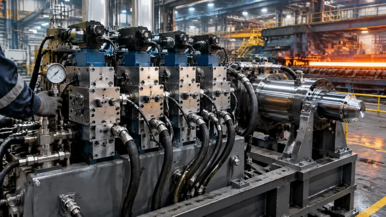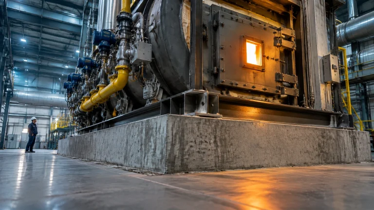
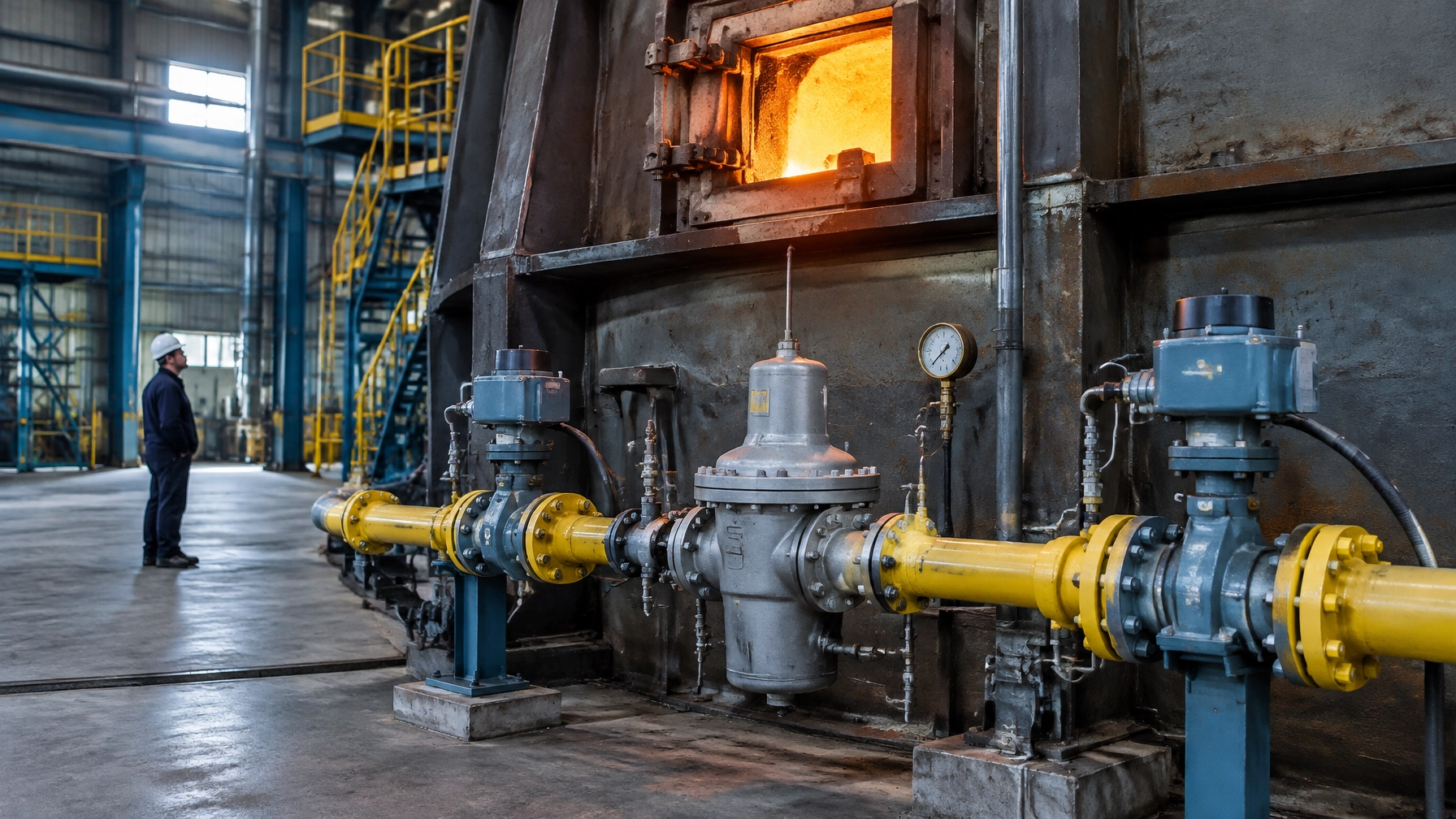
The fuel gas train is the least-owned and least-documented assembly on many furnaces, and one of the most consequential. It is often specified as catalogue components joined by pipe, selected on price or line diameter, and not re-verified after commissioning. Yet the train is not a row of components: it is a control loop. The pressure delivered at the burner is a band, not a constant, and the combustion curve is valid only for the pressure and gas composition present when it was commissioned.
This article does not revisit the burner management system and its safety interlock architecture, burner turndown and part-load combustion, combustion-air and flue-gas fan systems, the fuel meter as a legal emissions instrument under India’s carbon market, or furnace-conversion economics as such; it treats the gas train only as the mechanical and pressure interface on which those functions depend.
The figures below are readings of published standards and manufacturer data; they are not a substitute for OEM instructions, the structural or gas installation standard of record, the authority having jurisdiction, or a site-specific engineering review.
The Assembly Nobody Owns
The gas supplier’s obligation generally ends at the meter; the burner OEM’s specification begins at the burner inlet. The pipework and devices in between are often procured by a fabricator with no single party assigned ongoing ownership.
That middle section needs five things that are too often missing:
- A defined pressure band at the burner across the full firing range, not just a regulator setpoint at one flow.
- A fuel-quality envelope that describes the range of gas properties the burner must accommodate.
- A documented trip and proving regime with test results, not just a list of installed devices.
- A maintenance and spares plan for filters, regulators, sensing lines and safety devices.
- A named owner responsible for setpoints, verification and records.
The Regulator Is a Proportional Device, Not a Constant
Under EN 334, accuracy class (AC) describes the maximum permissible positive or negative deviation of outlet pressure from setpoint under stable conditions, expressed as a percentage of setpoint. AC 5 means ±5%; AC 2.5, AC 10 and AC 20 are other examples. Lock-up class (SG) describes the maximum permissible rise above setpoint at zero flow: SG 10 limits that rise to 10%. Both have a 1 mbar minimum deviation value.[1]
For illustration, a regulator set to 100 mbar with AC 5 permits an outlet pressure from 95 to 105 mbar under the applicable stable conditions. At zero flow, SG 10 permits lock-up pressure up to 110 mbar. Those figures describe different operating conditions: accuracy under flow and lock-up at zero flow.
As flow rises, outlet pressure falls. This behaviour (called droop, offset or proportional band) is a characteristic of the regulator, not an anomaly. A tighter droop requirement can call for a lighter spring, larger diaphragm, or pilot-operated or dome-loaded design rather than a direct-operated regulator. Oversizing can cause instability, faster wear, higher lock-up pressure and hunting: unstable oscillation of the regulator mechanism. Size on the smallest orifice that passes maximum flow, and do not select a regulator larger than the pipe it sits in.

A setpoint that keeps being raised to recover heat input is often a symptom, not a solution. Check for an undersized regulator, a loaded filter or utility inlet pressure below the contract minimum before changing the setpoint.
What a Regulator Is Not
A regulator is not an isolation valve. A soft-seated regulator may approach ANSI/FCI Class VI shutoff performance, but it is not intended to serve as a block valve. Seat leakage can appear as downstream pressure creep; internal relief devices exist because the seat can leak.
Its vent must also remain clear so the regulator can breathe and any internal relief can function. Blockage by ice, insects or debris can contribute to hazardous overpressure. Vents should face downward; a vent line must be at least the size of the regulator vent connection, run independently to a safe location, and terminate away from ignition sources, building openings and air intakes. Blanking or plugging a vent “to stop the smell” turns a nuisance into a hazard.
Table 1. Gas train components: assumption versus evidence
| Gas train component | What it is usually assumed to be | What it actually is | The failure it causes when it is wrong | The check that proves it |
|---|---|---|---|---|
| Pressure regulator | A constant-pressure device | A proportional device with droop and lock-up limits | Unstable or incorrect burner input | Record inlet/outlet pressure across firing range and verify class |
| Slam-shut or safety shut-off device | A device that will trip when needed | A pressure-sensing protective device with a declared trip response | Overpressure reaches downstream equipment | Witness a trip on its own sensing element and record reset |
| Filter and strainer | Routine maintenance hardware | A pressure-loss element protecting downstream trim | Reduced regulator inlet pressure and heat input | Trend differential pressure; inspect element condition |
| High and low pressure switches | Fixed settings from installation | Protective limits derived from burner pressure requirements | Unsafe or nuisance shutdowns | Function-test and compare dated settings with burner data |
| Valve proving system | Automatic proof of safety | A leak test of shut-off valves and inter-valve pipework | Leakage goes undetected or sound valves lock out | Validate test against installed volume and record results |
| Gas meter | A complete measure of heat input | Usually a volume reading requiring gas-quality context | Energy delivery is inferred inaccurately | Compare meter data with composition and calorific value |
The Filter Is a Combustion Variable
A 50 micrometre filter element is a typical baseline for protecting regulators and valves; a coarser, roughly 400 micrometre Y-strainer can provide pre-cleaning. A clean-element pressure drop is normally targeted at no more than about 10 mbar, with service triggered by the manufacturer’s differential limit.[2]
A differential gauge is valuable as a trend, not automatically as a trip. A rising reading can reveal progressive loading; element collapse or damage can allow contamination downstream. Construction debris can migrate through a system for years after installation. Filter inspection must therefore include the housing, element and evidence of liquid or debris, not only the gauge.
A dirty filter is a combustion component, not simply a maintenance item: element loading raises pressure drop → regulator inlet pressure falls → outlet pressure falls at a given flow → heat input changes at every valve position.

Proving the Safeguards Instead of Trusting Them
EN 746-2’s industrial thermoprocessing gas-train requirements, now superseded by EN ISO 13577-2, describe expectations including an inlet manual isolating valve, filter, regulator, two automatic safety shut-off valves per burner and high- and low-pressure switches. For burners above 1200 kW, the cited requirements call for valve proving.[3]
Under EN 1643, valve proving must detect and signal leakage in shut-off valves or the pipework between them. Leakage above 0.1% of maximum flow rate must prevent start-up or cause fault lockout.[4] A practical reasoning point matters here: valve proving is a pressure-decay test on a fixed volume, so the pass/fail result depends on trapped volume and test pressure. Validate factory-default parameters against the installed pipework; defaults can pass a real leak or reject a sound valve when the volume is very small or large.
Two shut-off valves in series protect against a single valve failure only if leakage between them is proved. Valve proving is the routine evidence, and often the first function disabled when nuisance trips begin.
EN 14382 defines accuracy group (AG) for trip accuracy. Functional class A devices must shut off automatically if the pressure-sensing element is damaged or external power fails, and reset manually. Response time is the interval from pressure reaching the permissible limit at the sensing point to complete closure. The standard requires the value to be tested and declared rather than setting one universal limit; industrial applications commonly target around two seconds.[5]
A proof of closure shows that a device moves to its closed position; a proof of tightness checks leakage. Closing an upstream valve to test a slam-shut proves the pipework’s response, not that the slam-shut trips on its own sensing element.
Commissioning practice commonly sets the low gas pressure switch at 50–70% of normal operating pressure and the high switch at 120–150%, with the high setting below the rating of the weakest downstream component. These settings must derive from the burner’s own minimum and maximum manifold-pressure data, not a fitter’s previous job. Record each setpoint with its date and signature.
The Only Fuel Property the Burner Sees
The Wobbe index is gross calorific value divided by the square root of specific gravity relative to air. For gas at 38 MJ/Nm³ gross calorific value and 0.6 specific gravity, the index is about 49 MJ/Nm³. Typical pipeline natural gas is roughly 48–53 MJ/Nm³, corresponding to EN 437 family 2H.[6] A commonly cited interchangeability band is about ±5%, subject to the burner manufacturer’s limits.[7]
Through a fixed orifice at fixed supply pressure, heat input is proportional to Wobbe index. That is why Wobbe index, not calorific value alone, is the interchangeability parameter.
This is where the energy transaction and the flame can stop agreeing: gas is bought and billed by energy, while a furnace often controls pressure or volume. Without calorific-value measurement, heat input is inferred rather than known. As a reasoning illustration, at constant volumetric flow a 5% fall in calorific value reduces heat input by about 5%; stoichiometric air demand per cubic metre also falls, shifting the air–fuel equivalence ratio by roughly 5% in the same direction. A furnace trimmed to a thin excess-oxygen margin has little room for that change.
Table 2. Fuel-gas parameters for the furnace specification
| Fuel gas parameter | What it is | Typical pipeline natural gas value | What a hydrogen blend does to it | Why the furnace specification needs it |
|---|---|---|---|---|
| Wobbe index | Gross calorific value divided by square root of relative density | Roughly 48–53 MJ/Nm³ | Generally decreases; 20% H₂ lowers it roughly 3–5% | Indicates heat-input interchangeability at fixed nozzle conditions |
| Gross calorific value | Energy released per standard volume | Gas-dependent; example: 38 MJ/Nm³ | Falls as hydrogen share rises | Determines energy delivered per unit volume |
| Specific gravity | Gas density relative to air | Example: 0.6 | Falls as lighter hydrogen is blended | Affects flow and Wobbe calculation |
| Hydrogen fraction | Volume fraction of hydrogen in the fuel | Utility-declared; not presumed | Rises by definition | Identifies the blend the burner must accommodate |
| Hydrocarbon dew point | Temperature at which hydrocarbons may condense | Around −2°C (cricondentherm) | Blend-dependent; specify and verify | Helps prevent liquid dropout |
| Water dew point | Temperature at which water may condense | Around −8 to −10°C at maximum operating pressure | Blend and supply treatment dependent | Helps reduce hydrate and ice risk |
When the Pipe Starts Carrying Hydrogen
A 20% hydrogen blend by volume can lower Wobbe index by roughly 3–5%; one analysis reports about 4.9% lower than pure methane.[8][9] Through a fixed nozzle at constant pressure, volumetric flow tends to rise because hydrogen is much less dense, but energy per unit volume falls. At unchanged supply pressure, thermal input typically drops.
The flame behaviour changes too. At atmospheric conditions and stoichiometric mixture, laminar flame speed is roughly 0.40 m/s for methane and 3.25 m/s for hydrogen.[10] Hydrogen addition raises methane’s laminar burning velocity broadly in proportion at low fractions, increasing flashback risk, particularly on premixed and partially premixed burners.[8]
Plants should ask the utility for a range and rate of change, not just an average. Write a fuel envelope into the furnace specification that includes Wobbe and calorific-value ranges, hydrogen fraction, specific gravity and dew points. A fuel change is a recalibration event, not a tuning tweak.

Cold Gas in a Cold Climate of Its Own
Pressure reduction causes Joule–Thomson cooling, commonly quoted at 6–8°F per 100 psi, or about 0.5–0.65°C per bar.[11] That is why ice and hydrates can form at the regulator seat, the train’s coldest point, rather than along the pipe. Typical specification values include a hydrocarbon dew point around −2°C and a water dew point around −8 to −10°C at maximum operating pressure.[12]
Look for an oil film in the filter housing, liquid in the drip leg, damaged seats or fouled burner nozzles. Standing remedies include line heating, dehydration and, where engineered and approved, inhibitors.
Where the Energy Bill and the Flame Stop Agreeing
Thermal mass flow meters measure mass directly without separate pressure and temperature compensation; typical turndown is of the order of 100:1, with almost no permanent pressure drop. Orifice plates measure volume, need compensation to derive mass, have more limited turndown and weaker low-flow sensitivity, and impose permanent pressure loss. Online gas chromatographs or correlative calorific-value/Wobbe analysers let combustion control apply gas-quality feed-forward before the burner sees a change.
Pipe velocity is also a design variable: about 20 m/s is a common ceiling in lower-pressure gas pipework; up to about 40 m/s may be accepted at higher pressure where filtration is fine enough to protect valves and trim. Excess velocity first announces itself as noise, then as erosion.
The Gas Train as a Standby Risk
The event that stops production is often not a regulator failing outright. It is the absence of the correct diaphragm, filter element, seat kit or spring range, and no recorded setpoints to restore the system. The operational consequence is measured in available tonnes and lost campaigns, not merely in a replacement component. A documented spare strategy protects continuity as well as equipment.
Where This Lands Across Furnace Applications
A steel rolling mill depends on repeatable heat input across changing production demand, while heat treatment furnaces need stable combustion conditions for controlled thermal cycles; an aluminum melting furnace and a melting furnace for steel have distinct duty and fuel demands. The same disciplined fuel envelope matters in thermal processing equipment, a hot dip galvanizing plant, a metal recycling furnace, and industrial furnace systems, because a pressure band that was never documented at commissioning also decides how long furnace spare parts survive in service. For an industrial furnace manufacturer, designing for traceable pressure and fuel-quality limits supports the wire and cable industry as well as other continuous-process operations.
What to Keep on the Shelf
Maintain a spares and records package matched to the installed train. Continental Furnaces’ furnace spares and accessories page outlines the company’s broader supply and replacement support.
- A complete regulator with the correct spring range, plus a second seat kit.
- The specified slam-shut device and its sensing line.
- Filter elements at the installed micron rating, a differential gauge and a spare gauge.
- Pressure-switch setpoints recorded on a tag at each device.
- A valve-proving test record template with installed pipework volume filled in.
- Vent-line caps and insect screens.
- A calibrated differential-pressure manometer.
- The as-built gas-train drawing, with every setpoint dimensioned.
The cheapest item on that list is the record of setpoints.
From Belief to Evidence: A Five Phase Gas Train Programme
- Document: Tag every component and record every setpoint with a date.
- Measure: Log filter differential, regulator inlet and outlet pressures across the firing range, burner manifold pressure at high and low fire, and gas composition.
- Size and set: Check the regulator at minimum inlet pressure and maximum flow; verify droop against its class, match the spring range, and derive switch settings from burner data.
- Prove: Trip the slam-shut on its own sensing element, validate valve proving against trapped volume, inspect vent lines and conduct an annual independent leak test.
- Govern: Put the fuel-quality envelope into the supply contract, review composition annually, assess hydrogen readiness and treat fuel changes as recalibration events.
Build a Fuel Path You Can Defend
Continental Furnaces brings 35+ years of experience, ISO-certified quality and prompt service to industrial thermal-processing partnerships. Give the fuel path the same engineering attention as the furnace it serves: request a quote to discuss your application and build a verifiable basis for sustained competitive advantage.
References
- BS EN 334:2019, Gas pressure regulators for inlet pressures up to 100 bar.
- Honeywell Kromschröder, EN 746-2 gas train requirements: filter and strainer.
- Honeywell Kromschröder, EN 746-2 gas train requirements: valve proving system.
- BS EN 1643:2022, Valve proving systems for automatic shut-off valves.
- EN 14382:2019+A1:2024, Gas safety shut-off devices for inlet pressures up to 10 MPa.
- Wobbe index: definition, formula and typical natural gas values.
- MARCOGAZ, Guidelines for Industrial Gas: interchangeability and Wobbe index.
- The impact of hydrogen admixture into natural gas on residential and commercial gas appliances.
- Hydrogen blending in natural gas: technologies and challenges.
- Gas explosion basics: laminar burning velocities of methane and hydrogen.
- Welker, Freeze protection for natural gas pipeline systems and measurement instrumentation.
- IS 15127:2002, Natural gas: quality designation.