25 October 2026 | Morning Edition
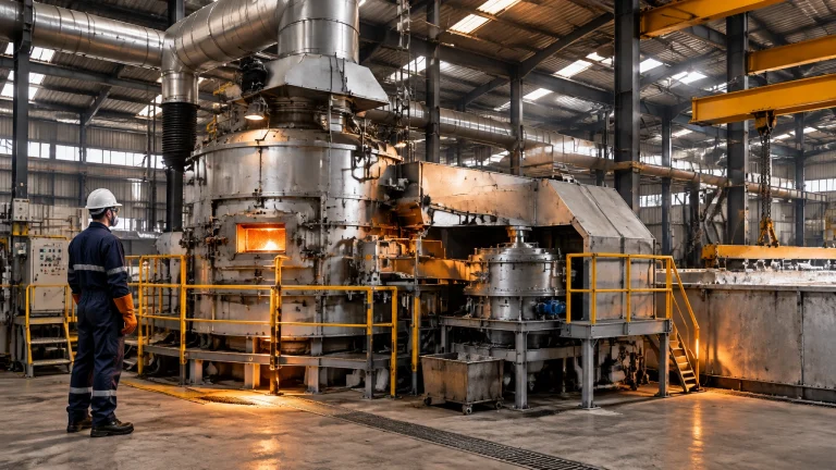
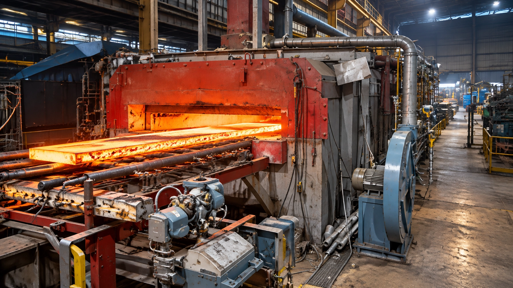
In a reheating furnace, some of the heat operators work hard to put into steel leaves through a less visible route: the cooling water protecting skid pipes and other hot-zone components. For steel rolling mills, managing that heat is not simply a matter of adding insulation. It requires coordinated decisions about refractory design, cooling-circuit reliability, water quality, product quality and recovery opportunities.
The stakes are significant. Technical papers report that skid-pipe cooling can account for around 10–15% of a reheating furnace’s heating energy, with one steel-industry white paper describing a range of 10–17%, depending on the installation. Well-designed heat-loss engineering can reduce that burden while protecting the equipment that keeps production running.

Where furnace cooling-water losses occur
Cooling water removes heat from components exposed to severe furnace conditions. In a rolling mill, skid pipes support and transport slabs or billets through a reheating furnace. The cooling protects the steel structure, but the system also carries away energy that could otherwise contribute to heating the charge.
Other important areas include:
- EAF water-cooled panels, where circuit performance and leak prevention are essential to safe operation.
- Melting furnace for steel and non-ferrous duty, where coil, shell and door cooling on an aluminum melting furnace or a metal recycling furnace protects coil insulation and surrounding components.
- Induction furnace coils, which must shed heat reliably to protect coil insulation and surrounding components.
- Pumps, hoses, heat exchangers and manifolds, where poor flow, deposits or leakage can turn a cooling loop into a reliability risk.
A useful baseline is to track water flow and the temperature difference between circuit inlet and outlet. These readings help identify changing heat extraction, but they should be interpreted alongside production rate, furnace conditions and circuit design, not as standalone measures of efficiency.
Engineering response: insulation, cooling circuits and water quality
1. Insulate skid pipes for the furnace environment
Modern skid-pipe insulation uses engineered refractory shells designed for high temperature, mechanical loading and scale exposure. Prefabricated modular shells can also simplify replacement and reduce work during planned shutdowns.
Published industrial cases provide useful benchmarks, but they are not universal guarantees:
- At ArcelorMittal Bremen, a lightweight prefabricated shell system reduced measured skid-system heat loss by 35% compared with the previous insulation arrangement. The paper reports payback in less than one year for that installation.
- At voestalpine Linz, a 110 t/h pusher furnace achieved a reported 21% reduction in overall skid-system energy loss after a lightweight insulation upgrade. Some areas could not use the same lining, limiting the achievable saving.
- Test-furnace and CFD comparisons reported heat-loss reductions above 50–60% for particular lightweight-shell designs against dense castable. These are comparison results for specified conditions, not a promise of the same reduction at every plant.
The distinction matters: these figures describe skid-system heat loss, not an equivalent percentage reduction in total furnace fuel use. A site assessment should establish the current baseline and calculate savings against the actual operating profile.
2. Keep cooling circuits closed, controlled and maintainable
Closed-loop cooling reduces routine water consumption and helps limit contamination, corrosion and scaling. In induction furnace coil cooling, it is especially important to maintain the water chemistry and flow requirements specified by the furnace and power-supply OEM. The same discipline applies to quench, radiant-tube and fan-shaft circuits on heat treatment furnaces serving the wire and cable industry, where dependable cooling keeps thermal processing equipment available through demanding production cycles.
A Columbia Steel technical paper notes that many manufacturers recommend coolant conductivity below 10 µS/cm for the systems it discusses. That is a useful caution against treating 200–300 µS/cm as a suitable target: those levels were associated with problems in the paper’s operating experience. Always follow the relevant OEM specification, since allowable chemistry varies by equipment and circuit.
Hardness limits are also not one-size-fits-all. Use an agreed water-treatment program and monitor parameters such as conductivity, hardness, pH, temperature and flow. Scale deposits can impede heat transfer; a 1 mm layer is sometimes cited as reducing heat-transfer performance by up to 30%, but the actual impact depends on deposit properties and component geometry. Inspection and trend data should guide cleaning decisions.
Water chemistry also shapes component life, not just heat transfer. A JFE Steel technical report on circulatory cooling for reheating-furnace skid pipes found that adjusting the Langelier index from −0.9 toward mildly scaling values, with a calcium dispersant and a corrosion inhibitor, cut measured corrosion rates to below one-hundredth of the original level in hot-jar testing. Corrosion behaviour also depended on flow velocity and temperature, so chemistry targets should be set against each circuit's actual operating conditions rather than copied from another plant.
3. Recover heat without compromising component protection
Where cooling water is hot enough, a separate heat exchanger can transfer energy to a useful process or a low-temperature power-generation system. Climeon’s steel-industry white paper describes ORC-based recovery from hot water in the 70–120°C range. It estimates that a 150 t/h reheating furnace could produce up to 1.1 MW of electricity under the stated conditions, alongside a roughly 10% reduction in cooling requirement. These are supplier estimates; actual output depends on available heat, flow, operating hours and integration design.
Keep the recovery circuit separate from the equipment-protection loop where required. Thermal recovery must not compromise minimum flow, allowable pressure, coolant temperature or emergency cooling capacity.

Skid marks: managing heat loss and product quality together
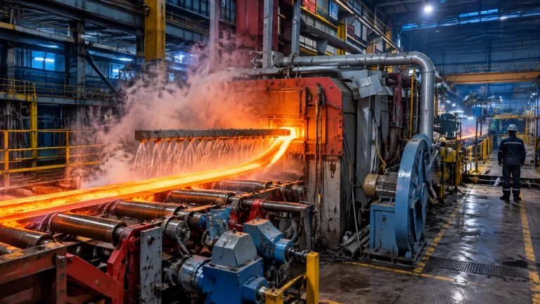
Skid contact can create colder regions, often called skid marks, in reheated slabs. These temperature variations may increase the time needed to achieve the target temperature and can affect downstream rolling quality.
Rider geometry, contact conditions, insulation and furnace operation all influence the result. A 2025 CFD study found that raising skid coolant temperature to 350°C could reduce reheating time by approximately 4–5% in the modeled case, while reducing cold-spot severity. This is a research result, not a general operating instruction. The study’s high-temperature approach requires a detailed review of coolant choice, pressure, materials, controls and safety; it should not be interpreted as a recommendation to raise the temperature of a standard water circuit. The cited paper does not establish a universal 75–80% reduction in skid-mark intensity.
Cooling-water improvement options at a glance
| Intervention | Conventional approach | Modern engineering response | Evidence and business relevance |
|---|---|---|---|
| Skid insulation | Aging or dense lining; frequent repairs | Prefabricated, application-specific refractory shells | Reported skid-system savings: 35% at ArcelorMittal Bremen and 21% at voestalpine Linz. Site-specific payback in both papers was about one year or less. |
| Closed-circuit cooling | Greater exposure to contamination or routine water loss | Controlled loop with suitable pumps, heat exchangers and monitoring | Improves protection and operating control; benefits depend on system design and maintenance. |
| ORC heat recovery | Reject usable hot-water heat to cooling equipment | Transfer suitable heat through a separate recovery system | Climeon describes 70–120°C input water; power output and payback require a site study. |
| Water-quality program | Reactive response to fouling or conductivity alarms | Routine testing against OEM limits, with treatment and filtration | Helps protect heat transfer, coil integrity and availability; no single chemistry limit suits every circuit. |
| Rider and anti-skid-mark design | Accept recurring cold spots as a furnace constraint | Review rider geometry, contact and thermal profile together | Can support uniform reheating and product quality; quantify benefits through plant trials or validated modelling. |
A phased roadmap for plant teams
Phase 1: Assessment and planning
Map cooling circuits and protected components. Record flow, inlet and outlet temperatures, operating hours, conductivity and maintenance history. Establish a baseline against production rate and fuel or power consumption.
Phase 2: Prioritise engineering changes
Inspect skid-pipe insulation and high-wear areas. Review circuit isolation, monitoring and water treatment. Rank projects by energy potential, downtime risk, product-quality impact and installation access.
Phase 3: Design and integrate
Specify materials, shells, pumps, hoses and heat exchangers for the actual service conditions. Evaluate heat recovery only after confirming stable heat availability and preserving critical cooling capacity.
Phase 4: Commission and verify
Measure performance before and after changes under comparable operating conditions. Track skid-system heat loss, fuel per tonne, circuit temperatures, maintenance hours and slab-temperature consistency.
Phase 5: Sustain performance
Use inspections and operating data to detect deteriorating insulation, deposits, leaks or flow imbalance before they cause unplanned downtime.
Build reliability into the spares strategy
Furnace cooling systems need the right parts available before a failure becomes a production stoppage. Critical furnace spare parts may include water-cooled panels, skid pipes, insulated riders, non-conductive hoses, pumps and heat exchangers, alongside the dampers, valves and instrumentation that tie modern industrial furnace systems together. Match spare specifications to operating temperatures, chemistry, pressure and equipment interfaces; compatibility is as important as availability.
For plants investing in heat treatment furnaces or melting furnaces and recycling projects, cooling-water management belongs in the lifecycle plan from the outset, not as an afterthought during maintenance.
Turn heat losses into a measured improvement plan
Cooling-water management connects efficiency, yield, reliability and sustainability. The strongest results come from treating insulation, water chemistry, circuit integrity, product quality and heat recovery as one engineering programme.
As an industrial furnace manufacturer with 35+ years of expertise, Continental Furnaces delivers customized thermal-processing solutions across the steel rolling mill, heat treatment, melting, galvanizing and hot dip galvanizing plant sectors, backed by ISO-certified quality and prompt service through design, installation and lifecycle maintenance. Consult our team to assess your furnace cooling circuits and identify a practical route to sustained competitive advantage. Request a project consultation.
Technical references
- Almatis: ArcelorMittal Bremen skid-pipe insulation case study
- Almatis: voestalpine Linz pusher-furnace case study
- Climeon: The Power of Hot Water, steel-industry white paper
- Ahmed et al.: Skid coolant temperature and reheating-furnace performance, Thermal Science and Engineering Progress (2025)
- Columbia Steel: Induction furnace cooling systems
- JFE Steel: Designing water quality of circulatory cooling systems for reheating-furnace skid pipes