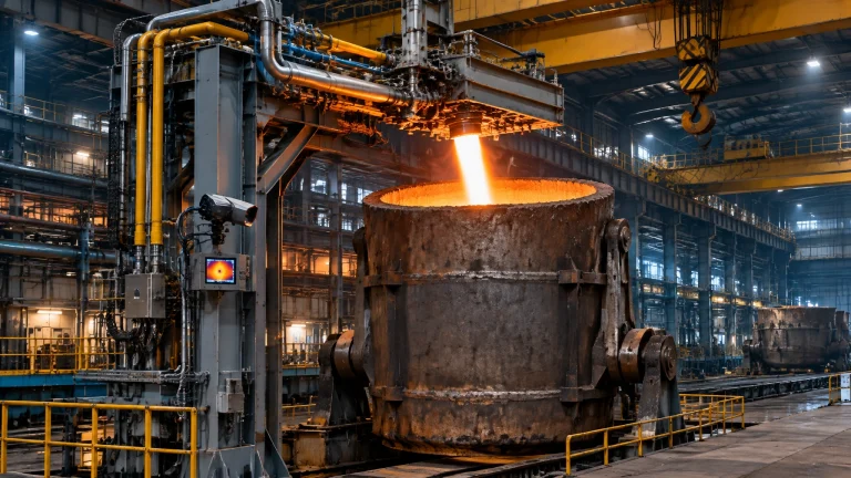
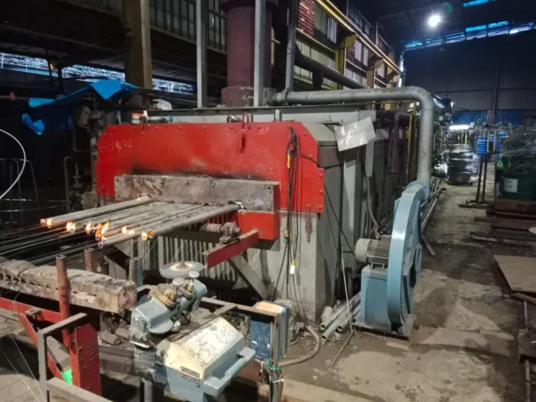
Furnace pressure is easy to overlook until fuel use climbs, temperature uniformity drifts or operators find hot-gas leakage around doors and joints. In fuel-fired industrial furnace systems, pressure control and sealing work together: a poor setpoint can pull cold air inside, while inadequate seals let valuable heat escape.
For plant managers and maintenance teams, the goal is not simply to “run positive.” It is to maintain the pressure profile required by the furnace design and process, control infiltration at the main leakage points, and verify performance using reliable measurements. The U.S. Department of Energy (DOE) notes that air infiltration in a poorly maintained high-temperature furnace can increase fuel consumption by as much as 10%. That is a potential loss, not a guaranteed saving from any single retrofit.
Why furnace pressure matters
Hot flue gases rise through the stack, creating a natural draft, or stack effect. An induced-draft fan can increase that pull. When pressure inside the furnace is below ambient at a door, joint or penetration, outside air is drawn in. The furnace then spends fuel heating that cold air toward exhaust temperature before it leaves through the flue.
The pressure difference is not uniform from floor to roof. Pressure changes with elevation, so a reading at the stack or roof may not represent conditions where the largest leaks occur, often around the hearth, doors or charging openings. A difference of just a few mm water column (mmWC) can significantly affect airflow through an opening. The fuel impact depends on opening area, furnace temperature, leakage duration, draft system and production duty. As a screening estimate, plants may investigate losses in the low single-digit to roughly 10% range on leaky, high-temperature equipment; confirm the actual figure through measurement and normalized fuel data.
Neutral or slightly positive pressure at a critical leakage plane may suit some furnaces, but it is not a universal rule. Some equipment must operate slightly negative to prevent flue gases escaping into the work area. Setpoints must follow the furnace design, process requirements and combustion-safety strategy.
Quantifying the hidden cost: a worked illustration
Consider an illustrative 0.25 m² effective opening with a 5 Pa pressure difference across it. Using a simplified orifice-flow estimate, discharge coefficient 0.6 and ambient-air density 1.2 kg/m³, airflow is approximately 0.43 m³/s, or 1,560 m³/h. This is a screening calculation, not a prediction for every open furnace door; real flow varies with geometry, pressure distribution, buoyancy and door position.
Heating that air from 25°C to process-temperature-level exhaust conditions requires substantial heat:
| Illustrative furnace condition | Approx. sensible heat to raise incoming air | Approx. fuel input at an assumed 80% delivery efficiency |
|---|---|---|
| Heat treatment furnace, 900°C | 450 kW | 565 kW |
| Steel rolling mill reheat furnace, 1,100°C | 560 kW | 700 kW |
| High-temperature duty, 1,250°C | 635 kW | 795 kW |
These are instantaneous illustrative rates while the assumed airflow persists. The estimates use air’s approximate specific heat of 1.0 kJ/kg·K and exclude other losses; actual fuel demand depends on furnace performance and operating conditions. A melting furnace for steel, aluminum melting furnace or metal recycling furnace also has its own airflow, opening and process profile. Use site measurements rather than directly transferring this example.
Door-open time is a controllable variable. Coordinate charging and discharging, prepare the next load in advance, avoid holding doors open between moves, and log open duration by shift. In melting operations, shorter unnecessary openings can also reduce heat loss and help limit dross formation; the primary focus here remains pressure and infiltration.

Pressure control architecture: measure at the process plane
A reliable control loop starts with a correctly located, maintained pressure tap. Position the tap at or near the hearth level or major leakage plane, and use additional measurement points where furnace size or geometry creates meaningful pressure gradients. Protect taps from blockage and heat damage, and check transmitter zero and calibration during planned maintenance.
In a balanced-draft installation, combustion-air flow is managed separately from furnace draft. A pressure controller typically adjusts the induced-draft fan or stack damper; feed-forward from firing-rate or combustion-air demand can help anticipate disturbances, while PID feedback trims pressure to setpoint. The control must respond across the operating range, including low firing rates and charge/discharge events.
Pressure management also interacts with combustion-air/fuel-ratio control and excess-O₂ trim. Flue-gas O₂ trends can help identify changes, but high O₂ alone does not prove infiltration: burner excess air, sampling location and operating rate matter. Review O₂ alongside CO, pressure, fuel flow and firing conditions. Any control change must preserve stable combustion and safe management of potentially escaping hot gases.
Atmosphere-sensitive processes deserve extra attention here. Bright annealing lines serving the wire and cable industry run protective atmospheres where even minor air ingress can downgrade surface finish, so pressure integrity is a quality parameter, not only an energy one.
For a practical reference, the DOE furnace pressure guidance recommends monitoring pressure near leakage points and describes automatic pressure control. Siemens’ furnace draft control application note discusses measurement location, pressure gradients, feed-forward and PID control.
Sealing systems and door discipline
Pressure control cannot compensate for deteriorated hardware. Inspect door interfaces, seals and penetrations as a system:
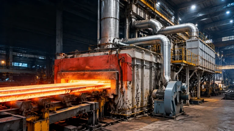
- Doors and charging openings: Check fibre or water-cooled seals, alignment, pneumatic clamping and closing force. For walking-beam and pusher reheat furnaces, verify hearth and side seals while accounting for movement, scale and product passage.
- Small openings: Close peep and sight doors when not in use. Keep thermocouple wells, cable glands and instrument penetrations properly sealed, without compromising safe access or measurement.
- Special applications: Sand or blade seals may be appropriate on some galvanizing and melting furnaces. Review curtain-air arrangements and downcomer/damper design to prevent unwanted air paths.
- Operating events: Where feasible, sequence charge and discharge actions to reduce the time openings remain exposed. Check that door-position feedback, if fitted, reflects the actual door state.
A well-engineered hot dip galvanizing plant also benefits from attention to openings and pressure balance around heated process areas.
Condition monitoring and source comparison
Trend furnace pressure continuously where instrumentation allows. During inspections, use safe, approved methods: smoke or tissue indicators can reveal airflow at accessible cool-side joints, while thermal imaging can identify unusual temperature patterns around door surrounds and roof penetrations. Do not expose personnel or instruments to hot gases; follow site safety procedures. Include a leakage audit in turnaround scope, when access is available for closer inspection.
| Infiltration source | Typical impact | Management focus |
|---|---|---|
| Main doors and charge/discharge openings | Potentially high fuel loss; temperature disturbance and unstable pressure during moves | Seal condition, clamping, door alignment, open-time logging |
| Peep and sight doors | Local air entry; possible atmosphere and temperature disturbance | Closing discipline; routine visual inspection |
| Roof penetrations and structural joints | Persistent leakage; pressure-control variation | Thermal survey, casing and joint repairs |
| Thermocouple and cable glands | Local infiltration; unreliable measurements if seals degrade | Correct glands and penetration closure |
| Cracked brickwork or casing | Variable leakage; risk of hot-gas escape as pressure changes | Turnaround inspection and refractory/casing repair |
| Damper leakage or actuator faults | Draft instability and poor response to setpoint changes | Damper inspection, actuator testing and pressure trending |
Fuel-impact figures are furnace-specific. DOE reports that infiltration can raise fuel use by up to 10% in a poorly maintained high-temperature furnace; the table does not assign a fixed percentage to individual leak sources.
A four-phase pressure-management roadmap
- Phase 1: Baseline audit. Map pressure at relevant elevations; profile flue-gas O₂ and CO under representative loads; log door-open time and relate observations to firing rate and fuel consumption.
- Phase 2: Sealing and hardware remediation. Repair or upgrade seals, close redundant penetrations, inspect damper blades and verify actuator health before changing control settings.
- Phase 3: Control optimization. Confirm pressure-tap location, tune setpoints for the actual furnace and process, and integrate pressure control with combustion control without compromising safeguards.
- Phase 4: Sustained operations. Add leakage audits to turnaround work. Track pressure trends, excess O₂ and specific fuel consumption; train operators in door discipline and reporting seal damage.
For facilities evaluating thermal processing equipment upgrades, Continental Furnaces’ heat treatment furnaces are engineered for application-specific process requirements.
2026 outlook: smarter monitoring, stronger fundamentals
Modern furnace management systems can combine pressure transmitters, door-position/open-time sensors and continuous flue-gas O₂ measurement. Adaptive or model-predictive strategies may help anticipate pressure changes during firing and material movement; AI-assisted analytics can flag unusual pressure and fuel trends for inspection. These tools support, not replace, sound sensor placement, tested control logic and physical maintenance.
On new installations and retrofits, tighter casings, engineered air curtains and low-leakage dampers can strengthen performance when correctly selected for the duty. The fundamentals remain essential: seal leaks, measure at the right elevation, control pressure within approved operating limits, and verify results against production-normalized fuel data.
Build pressure control into an enduring partnership
Pressure and infiltration management is a lifecycle discipline, not a one-time control adjustment. As an ISO-certified industrial furnace manufacturer with 35+ years of experience, Continental Furnaces designs energy-efficient thermal processing equipment, provides prompt service support and maintains availability of furnace spare parts such as seals, dampers, actuators and pressure taps.
Discuss a pressure audit, retrofit or new furnace requirement with our team through the Continental Furnaces quotation page. Together, we can build an enduring partnership around reliable operation, lower avoidable fuel loss and sustained competitive advantage.