Afternoon Edition: 3 October 2026
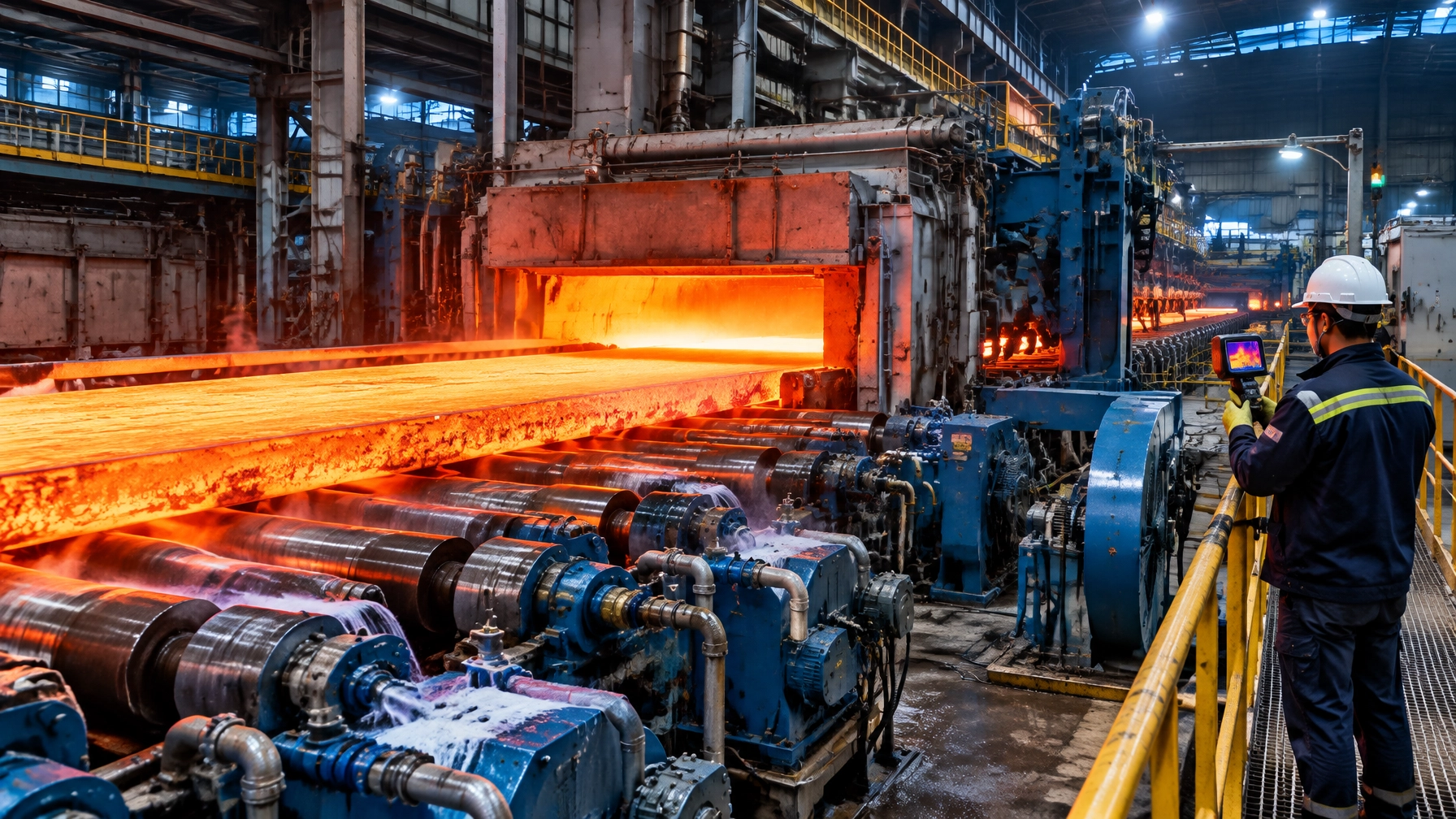
In a continuous thermal process, material handling is part of the metallurgical process. A hearth roll that bows by a few tenths of a millimetre, a bearing that overheats, or a cooling-water circuit that loses flow can create strip defects, unplanned stoppages and lost yield long before a major mechanical failure becomes visible.
For plant managers, maintenance heads and reliability engineers, the 2026 priority is clear: manage furnace rollers, walking-beam mechanisms, conveyors, skids, drives and bearings as one integrated reliability system. Mechanical availability, surface quality and energy intensity are inseparable KPIs.
With more than 35 years of experience in thermal processing, Continental Furnaces approaches this challenge through engineered design, condition monitoring, application-specific materials and responsive lifecycle support.
Why Furnace Material Handling Determines Plant Profitability
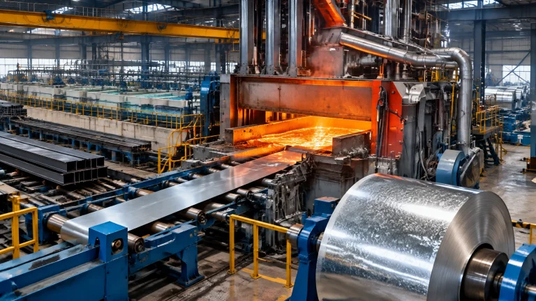
Roller-hearth and walking-beam systems operate under simultaneous thermal, mechanical and chemical stress. Depending on the furnace zone, roll surfaces may experience temperatures from approximately 700°C to 1,100°C, while reheating and specialized tunnel applications can impose substantially higher thermal loads.
The critical equipment set includes:
- Hearth rolls and water-cooled rollers
- Roller-hearth drives, couplings and gearboxes
- Walking beams, skids, skid buttons and hydraulic actuators
- Charge and discharge conveyors
- Pushers, transfer tables and chains
- Bearings, journals, seals and lubrication systems
- Cooling-water headers, hoses, flow meters and heat exchangers
- Refractories surrounding rolls, skids and charging points
- Fans, dampers and furnace-pressure equipment
These components support operations ranging from a steel rolling mill and continuous annealing line to heat treatment furnaces, a hot dip galvanizing plant, a melting furnace for steel, an aluminum melting furnace, a metal recycling furnace and high-throughput lines serving the wire and cable industry.
The Most Expensive Failure Modes
Thermal Fatigue, Bowing and Scale Build-Up
Repeated heating and cooling cycles create thermal fatigue cracks, surface checking and eventual spalling. Long rolls can also creep or bow under load, causing:
- Mis-tracking and uneven support
- Periodic marks on strip or bar
- Edge waves, scratches and surface pickup
- Contact with adjacent refractory or furnace hardware
- Increased drive torque and bearing loading
Scale and oxide deposits create another predictable signature. A nodule on a roll can imprint the strip at the roll’s circumference pitch. In galvanizing operations, zinc dross and coating residues can produce similar pickup damage.
Bearing Seizure and Drive Misalignment
Bearing failures commonly begin with rising temperature, contaminated lubricant, inadequate sealing or axial movement that the design cannot accommodate. Misalignment then increases vibration, torque and journal wear.
Critical warning indicators include:
- Bearing temperature rising more than 10°C above its established baseline
- Vibration increasing by 25% or more over a stable reference trend
- Abnormal motor current or gearbox torque
- Repeated chain elongation or coupling wear
- Visible axial movement, noise or irregular roll speed
Water-Cooling Loss and Thermal Shock
Water-cooled rollers provide a valuable solution where the roll surface temperature or load exceeds the practical capability of a solid roll. They also introduce a second reliability system.
A practical starting control envelope for many installations is:
- Cooling-water inlet: 25–35°C
- Outlet temperature: preferably below 45°C, subject to design limits
- Normal roll circuit temperature rise: approximately 5–15°C
- Flow alarm: below 90% of the commissioned baseline
- Pressure-drop trend: investigate any sustained deviation of 15% or more
- Water chemistry: controlled hardness, low suspended solids and filtration appropriate to the roll design
These are engineering starting points, not universal acceptance criteria. The final limits must follow the roll manufacturer’s thermal model and plant water chemistry.
Loss of flow, blockage or uneven distribution can cause local overheating. Excessive or uneven cooling can create thermal gradients that accelerate cracking. Flow, inlet temperature, outlet temperature and differential pressure must be trended together, not monitored as isolated readings.

2026 Inspection and Condition-Monitoring Standard
The modern approach combines physical inspection with operating data and product-quality evidence.
Recommended Inspection Intervals
For high-temperature, continuous-duty equipment, use the following as a structured baseline:
- Every shift: operator check of abnormal noise, smoke, tracking, drive load and visible water leakage
- Weekly: visual inspection of exposed roll ends, bearing housings, chains, guards and cooling connections
- Monthly: vibration and temperature trend review; inspection of drive alignment and lubrication condition
- Every 3–6 months: laser or dial-gauge straightness, runout and alignment checks
- At every planned outage: surface examination, nodule measurement, weld inspection, refractory clearance and cooling-circuit flushing
- Annually: full reliability review covering roll campaign life, failure history, spare coverage and replacement economics
Useful dimensional screening values include:
- Surface roughness intervention point: Ra above approximately 3.2 µm, subject to strip-quality requirements
- Nodule height intervention point: above approximately 0.2 mm
- Straightness concern: more than 0.5 mm deflection per 1,000 mm, subject to roll diameter, span and load
- Runout: establish a commissioned baseline and investigate any increase above the approved plant tolerance
Correlate Equipment Data With Product Defects
A reliable program links:
- Coil or batch number
- Furnace zone and roll position
- Defect location and pitch
- Roll speed and motor current
- Bearing temperature and vibration
- Cooling-water flow and temperature
- Furnace temperature and atmosphere data
A recurring defect at a constant pitch often identifies roll-surface buildup. Tracking problems concentrated in one zone point toward bowing, misalignment, skid wear or uneven support.
Legacy Practice Versus the 2026 Reliability Model
The following figures are business-case screening benchmarks, not guaranteed performance values. Actual results depend on furnace design, alloy, load, atmosphere, product mix and maintenance discipline.
| Metric | Legacy practice | 2026 reliability model |
|---|---|---|
| Typical roll campaign planning | 6–12 months | 12–24 months with zone-based rotation |
| Unplanned roll-related downtime | 24–48 hours/event | 8–16 hours through planned changeout and modular spares |
| Roll replacement cost | 100% full-roll replacement baseline | 70–90% of baseline where replaceable tires, collars or welded assemblies are feasible |
| Energy cost per tonne attributable to handling losses | Baseline | 5–12% reduction through alignment, reduced friction and fewer reheats |
| Inspection method | Periodic visual inspection | Online vibration, thermal, flow and torque trending |
| Maintenance decision | Replace after failure or visible damage | Dress, repair, rotate or replace using condition evidence |
| Labour requirement | Large reactive crew | Smaller planned team with lifting and roll-change automation |
The economic advantage is not only longer roll life. It is the combined reduction in rejected product, emergency labour, reheating, spare express freight and lost production hours.
Materials and Technology Updates for 2026
Modern industrial furnace systems increasingly use zone-specific materials rather than one alloy across the entire furnace.
Key options include:
- Cast Fe–Cr–Ni heat-resistant alloys for hot roll zones
- Higher-nickel and creep-resistant grades for severe service
- Alumina-forming or Ni–Al alloy systems where oxidation and pickup are dominant
- Ceramic or composite components where weight, insulation or oxidation resistance justifies their use
- Thermal-spray coatings to reduce adhesion, wear and cooling demand
- Fully welded, corrosion-resistant roll assemblies for improved sealing and maintainability
- Replaceable collars or tires to avoid scrapping an entire shaft
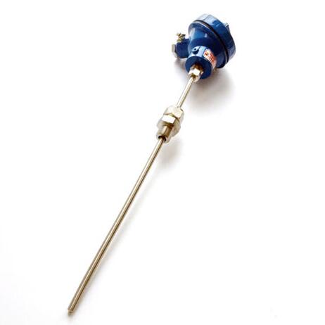
- Automated inline cameras, infrared sensors and vibration monitoring
- Assisted or automated roll-change tooling to reduce outage exposure

Ceramic and composite alternatives are not universal replacements for metallic rolls. They must be evaluated against impact loading, thermal shock, strip contact pressure, repairability and total installed cost. The correct decision is application-specific.
A Phased Reliability Roadmap
Phase 1: Assessment and Planning
Create an equipment register for every roll, bearing, drive, pusher, conveyor, skid and cooling circuit. Record:
- Design temperature and actual operating temperature
- Roll material, coating and dimensions
- Span, load and support arrangement
- Bearing type, lubrication and seal design
- Cooling-water flow, pressure and temperature
- Historical failure and replacement cost
- Critical spare availability
Phase 2: Baseline and Condition Monitoring
Establish commissioned baselines for vibration, temperature, motor current, roll runout and water flow. Install sensors first on the most critical rolls and high-consequence drives.
Set alarm levels using:
- Absolute limits
- Rate-of-change limits
- Deviation from baseline
- Correlation with product defects
Phase 3: Planned Repair and Replacement
Use a repair-versus-replacement matrix:
- Dress or grind minor surface buildup when geometry remains within tolerance.
- Repair or recondition bearings, journals and seals when damage is localized.
- Replace tires or collars when the shaft and cooling circuit remain fit for service.
- Replace the complete roll when cracks, excessive bowing, internal leakage or dimensional loss compromise integrity.
- Upgrade the alloy or coating when the same failure mode repeats after repair.
Phase 4: Spares and Changeout Readiness
Maintain a risk-ranked inventory of furnace spare parts, including:
- Critical rolls or replaceable roll tires
- Bearings, seals and journals
- Couplings, chains and sprockets
- Flow meters, valves and flexible hoses
- Skid buttons, pusher heads and refractory components
- Vibration and temperature sensors
A practical target is to hold one ready-to-install critical spare for every component whose failure can stop the line for more than 8 hours. Confirm lifting points, access routes, alignment tooling and roll-change procedures before the outage begins.
Phase 5: Review and Continuous Improvement
After every intervention, compare:
- Campaign life achieved
- Downtime hours
- Energy use per tonne
- Product rejection and surface defects
- Repair cost versus replacement cost
- Repeat-failure frequency
Use the results to update specifications for future thermal processing equipment and maintenance contracts.
Build Reliability Into the Furnace Lifecycle
The U.S. Department of Energy’s Process Heating Systems resources reinforce the importance of system-level assessment, measurement and efficiency improvement. For steel operations, the AIST furnace maintenance reference provides useful industry context for managing furnace mechanical risks.
Continental Furnaces, an ISO-certified industrial furnace manufacturer with 35+ years of expertise, extends this approach through customized engineering, responsive service and lifecycle support for rolling mills, foundries, galvanizing lines, recycling projects and the wire and cable industry.
Do not wait for a seized bearing, failed cooling circuit or bowed hearth roll to define your next shutdown. Contact Continental Furnaces or request a technical review through our consulting service. Share your furnace layout, roll drawings, operating temperatures, cooling-water data and failure history, and begin a reliability program built for higher yield, lower downtime and sustained competitive advantage.