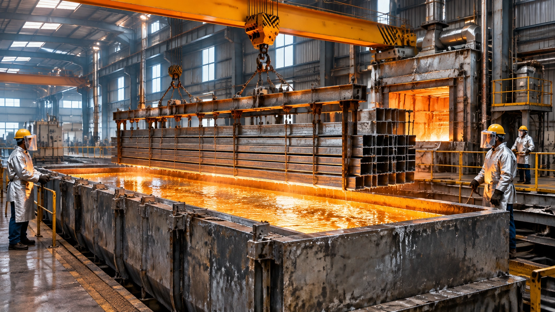
The kettle is the single most capital-consequential asset in a hot dip galvanizing plant. An unplanned failure can mean molten-zinc containment loss, emergency zinc handling, cleanup and an extended production outage. Potentially lasting months if replacement equipment and changeover resources are not ready. The central operating principle is straightforward: kettle life is managed, not left to luck. Heat-flux uniformity, temperature discipline, wall-thickness trending and planned replacement sequencing determine whether a kettle approaches its expected service life or fails prematurely.
All numerical figures in this article are indicative benchmarks from published surveys, plant reports and supplier references, not universal design limits. Results vary by plant, alloy and steel chemistry, line type, bath chemistry and throughput. Inspection and retirement decisions must be confirmed by the kettle designer and qualified engineering personnel.
Why kettle life is a capital-economics problem
The American Galvanizers Association’s (AGA) 2019 Process Survey reported an average kettle replacement life of 80.5 months, about 6.7 years. Its historical survey range was roughly 6–7 years. The survey collected responses from 53 of 169 plants, so use this as an industry reference, not a guaranteed life or plant-specific forecast. Read the AGA 2019 Process Survey.
Kettle life directly affects capital planning, production continuity and safety. A planned change allows a plant to sequence procurement, zinc transfer, lifting equipment and shutdown work. An unplanned leak can force the same decisions under emergency conditions, when access, specialist availability and production losses are harder to control.
The four failure modes
The AGA’s kettle failure lessons learned describes failure patterns including burner leaks, flow-related leaks, dross leaks and corner cracks.
- Burner leaks: A malfunctioning, misdirected or damaged burner can create localized overheating and rapid wall loss.
- Flow leaks: Poor circulation or unfavorable flow patterns can concentrate heat around corners and sharp transitions.
- Dross leaks: Persistent dross accumulation against the wall can promote localized attack and insulate the kettle from the bath.
- Corner cracks and thermal-stress fractures: Geometry, restraint and thermal cycling increase stress at corners. Heavy or poorly controlled charge immersion can add thermal shock.
The underlying mechanism is metallurgical as well as thermal. Iron solubility in zinc rises sharply with temperature, accelerating zinc attack as local temperature increases. Wall loss then reduces thermal resistance, allowing a thin area to heat faster than surrounding steel. The resulting hot spot can intensify and expand rapidly; a CFD study of kettle failure describes this feedback as exponential hot-spot growth. AGA failure lessons | CFD thermal analysis.
Temperature discipline and metallurgical limits
The operating band
A commonly cited operating range is 452–458 °C. Serious erosion accelerates above approximately 480 °C, with maximum attack reported near 530 °C. These are warning benchmarks, not permission to operate at the upper boundary. Control the bath to the process setpoint and avoid repeated overshoot. Kettle service-life guidance.
Kettle steel chemistry
Kettle material is typically specified as low-carbon, low-silicon steel. Higher silicon content can aggravate zinc attack. Welding must follow the kettle manufacturer’s specification and an approved welding procedure; low-silicon consumables, sometimes specified below 0.05% Si, may be required. Smooth internal weld profiles also help reduce sites where dross can accumulate. Confirm steel and filler chemistry with the kettle supplier before fabrication or repair.
Table 1: Heating approaches and wall-life considerations
| Approach | Heat-transfer character | Uniformity risk | Typical adoption / notes |
|---|---|---|---|
| High-velocity burners firing parallel to walls | Convective gas circulation redistributes heat around the kettle | Lower when designed, tuned and maintained correctly | Established gas-fired approach; burner position and furnace geometry matter |
| Direct radiant flame impingement | Concentrated local radiant heating | High; local overheating risk | Historical or poorly configured systems require particular scrutiny |
| Heat shields and spaced burners | Modifies or spreads the local heat input | Moderate; depends on spacing and shield condition | May reduce hot spots, but does not replace burner tuning or thermal mapping |
| Induction/electric heating | Direct or distributed electrical heat input | Potentially very uniform flux | Higher operating-cost exposure and more limited adoption; assess site energy economics |
High-velocity systems are not automatically safe: burner design, flame direction, refractory condition and maintenance determine actual performance. In one supplier-reported firing case, a pulse-fired design projected kettle life increasing from 5 to 6 years, or 20%; this is a design-specific estimate, not a general outcome. WesTech kettle-life paper. The AGA 2019 survey found flat-flame and end-fired high-velocity systems were each reported by about 52% of respondents, with overlap possible because some plants use multiple systems.
Condition monitoring: turn the wall into a measured asset
Ultrasonic thickness mapping
Create a repeatable inspection grid and record thickness at the same locations each time. Establish the baseline at installation or as early as practical, then trend the local loss rate in mm/year. A typical supplier-recommended interval is 2–3 years; inspect more frequently on older kettles or wherever thinning accelerates. That interval is a service recommendation, not a universal regulatory requirement. GIMECO KID inspection program.

Retirement criteria and complementary checks
A roughly 40% reduction in original thickness is cited as a typical retirement point, but minimum allowable thickness must be determined for the actual kettle, loading, condition and design. Sidewall thickness and integrity.
Use shell thermography to locate abnormal hot areas and temperature instruments to investigate them. A skin thermocouple reading around 25 °F / 14 °C above the surrounding bath can be treated as a critical hot-spot warning benchmark, not a standalone retirement limit. Confirm anomalies through engineering assessment and thickness measurement.
Table 2: Monitoring technique comparison
| Technique | What it detects | Typical cadence | Strengths / limitations |
|---|---|---|---|
| UT grid thickness mapping | Local remaining wall thickness and loss rate | About 2–3 years; increase frequency as risk rises | Quantitative and trendable; requires repeatable points and suitable access |
| Infrared thermography of shell | Surface temperature anomalies and possible hot spots | Periodic survey and after burner/process changes | Fast area coverage; finds thermal symptoms, not wall thickness |
| Bath / skin thermocouples | Bath control and local temperature deviation | Continuous or routine monitoring | Supports temperature discipline; placement and calibration matter |
| Visual / sounding / dross-depth checks | Deposits, deformation, leaks, changing dross depth | Routine operating inspections | Low-cost early warning; cannot replace NDT thickness assessment |
Operating practices that save kettle life
- Avoid unnecessary over-temperature excursions, especially during peak loading.
- Manage dross depth and remove deposits that remain against kettle walls.
- Maintain corner and bottom cleanliness; log dross depth consistently.
- Use controlled immersion practice and jig designs that limit thermal shock.
- Avoid localized heating during zinc addition and maintain even burner tuning.
- Investigate temperature or thickness anomalies promptly rather than normalizing them as routine.
This uniformity-first mindset also protects equipment in a steel rolling mill reheat operation and in heat treatment furnaces, where uneven heat affects both equipment life and product quality.
Planned replacement: a four-phase roadmap
Phase 1: Assessment
- Establish a UT grid and baseline thickness map.
- Survey shell temperatures and audit bath-temperature control.
- Log dross depth, burner condition and operating history.
- Estimate remaining life using local thinning rates, not an average alone.
Phase 2: Planning and procurement
- Place the kettle order with realistic lead-time allowance.
- Specify shell-steel chemistry and inspection documentation.
- Stock critical burner and combustion components.
- Confirm lifting, zinc-transfer and furnace spare parts readiness around the kettle cell.
Phase 3: Sequenced changeover
- Document melt-out, zinc transfer and emergency handling procedures.
- Follow the kettle manufacturer’s melt-out and installation schedule.
- Where specified by the manufacturer, delay final top-plate welding until the zinc is molten to accommodate thermal expansion.
- Coordinate commissioning, refractory checks and burner tuning before production restart.
Phase 4: Verification
- Re-establish the post-startup thickness baseline and temperature-uniformity profile.
- Track a KPI dashboard: shell hot-spot count, dross depth, wall-loss rate (mm/year) and energy per tonne galvanized.
- Assign owners and escalation limits for each KPI.
2026 technology and market updates
Condition-monitoring digitization
A May 2026 IEEE paper addresses ultrasonic wall-thickness measurement of hot-dip galvanizing kettles, reflecting growing interest in more repeatable, digitized inspection. IEEE paper, May 2026. GIMECO’s KID program offers a supplier example of mapped inspections and thickness trending; its published guidance recommends a 2–3-year inspection cadence, adjusted to kettle condition.
Failure prevention and safety resources
AGA and industry resources published in 2025 bring kettle-failure mitigation and workplace safety metrics into sharper focus. Use these to strengthen local inspection protocols, near-miss reporting and emergency response planning, not as a substitute for site-specific risk assessment. Industry resource note.
CFD-guided design and operating economics
CFD analysis can help engineers identify uneven temperature and heat-flux distribution before finalizing a furnace design or modification. The cited failure study used thermal analysis to locate a hot spot corresponding to the observed plant condition. IJIRSET CFD study. Separately, Faulhaber’s industry presentation discusses electric furnace options and homogeneous heat distribution as a kettle-life objective. EGGA presentation.
Disciplined temperature control increasingly supports energy-cost management and emissions compliance across thermal processing equipment and industrial furnace systems. Zinc-market volatility adds working-capital uncertainty, making kettle uptime more valuable; zinc prices move daily, however, and should be tracked separately from safety and maintenance decisions.
What this means for wire and cable galvanizing lines
Continuous wire galvanizing pots run for extended periods, so thermal uniformity, dross management and planned inspection are central to reliable production in the wire and cable industry. The same asset-care principles apply to customers operating a metal recycling furnace, an aluminum melting furnace or a melting furnace for steel: control heat input, trend equipment condition and plan service before failure. Explore hot dip galvanizing plant technology, Continental Furnaces’ heat treatment furnaces and metal recycling furnace solutions.
Conclusion: protect the asset, plan the next cycle
A kettle’s service life depends on heat-flux uniformity, controlled bath temperature, measured wall loss and timely replacement. With 35+ years of expertise, Continental Furnaces is an industrial furnace manufacturer supporting customized galvanizing furnace systems and related thermal-processing projects. Our goal is an enduring partnership focused on lifecycle value, prompt service and sustained competitive advantage.
Consult with our team to assess your furnace cell, monitoring plan or planned replacement scope. Request a quote and make kettle reliability part of your next capital and maintenance plan.