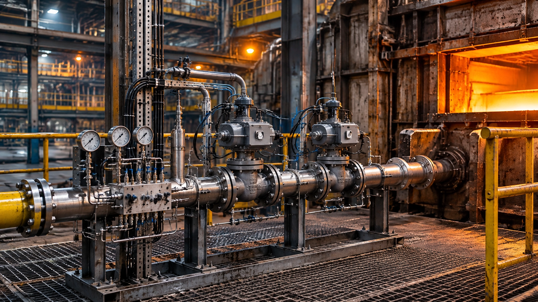
Hydrogen projects are often assessed first by their effect on burners. Yet the fuel train, the safety-critical boundary between gas supply and combustion, is where conversion work can succeed or stall. Hydrogen changes leakage behaviour, purge requirements, materials selection, detection and area classification before a plant changes its burner. The numerical values and time ranges in this article are indicative benchmarks drawn from published standards work, guidance, surveys, supplier references and peer-reviewed studies; actual requirements vary by plant, fuel composition, line type, throughput, pressure class and local regulation. Confirm every design against the applicable code edition, authority having jurisdiction (AHJ) and site-specific risk assessment. This is a practical guide to hydrogen readiness for thermal processing equipment, not a substitute for detailed engineering or approval.
Why the Fuel Train Is Where Hydrogen Projects Succeed or Stall
Hydrogen-enriched fuel can change volumetric flow, leakage behaviour, flame speed and flashback margins. It also places new demands on detection and materials. A natural-gas valve, seal or operating procedure should not be assumed suitable for hydrogen service just because it has performed reliably in the existing train.
NFPA 86’s fuel-train provisions, as applicable to the edition adopted locally, require safety shutoff valves to be proven closed before pre-ignition purge on equipment above 400,000 Btu/hr total capacity. This threshold is a code-linked reference, not a universal design limit; verify its application with the adopted edition and AHJ. Double block and bleed (DBB), two shutoff valves in series with a vent between them, is a common safety architecture. Annual seat-leakage testing is expected maintenance practice, subject to the equipment, applicable code and site programme. Current NFPA 86 development material points users toward NFPA 2 and ASME B31.12 for hydrogen and hydrogen-mixture piping; confirm which published requirements have been adopted for the project.[^1][^2]
What Hydrogen Changes in the Fuel Train, Component by Component
- Flow capacity: hydrogen’s lower energy per unit volume means a train may need roughly three times the volumetric flow for the same heat input on a pure-hydrogen basis. Treat this as an indicative engineering benchmark; confirm with fuel composition, pressure, burner demand and line sizing.
- Flammability and flame arresting: wider flammability limits affect hazard analysis. Where a flame arrester is required, hydrogen service requires suitable certification and selection for the gas group, including Group IIC where applicable.
- Flame detection: hydrogen flames can be nearly invisible in daylight. Specify and validate UV or hydrogen-compatible flame scanners.
- Gas detection: hydrogen supply is typically not odorised for industrial use. Provide dedicated gas detection rather than relying on smell.
- Seals and fasteners: elastomers can permeate or fatigue differently, while some high-strength steel parts are susceptible to hydrogen embrittlement.
- Vents and reliefs: route purge, bleed and relief discharges to safe, engineered locations. Do not vent into occupied spaces or assume an existing natural-gas vent is suitable.
Valve-Train Architecture: From Single SSOV to Segregated Hydrogen Trains
Double Block and Bleed and Valve Proving
A DBB arrangement places two automatic safety shutoff valves in series and provides a monitored vent between them. If the upstream valve leaks, the intermediate bleed provides a route for leakage rather than allowing pressure to build downstream. The vent must be correctly sized, monitored where required and routed to a safe location.
Include the manufacturer’s valve-proving and proof-of-closure requirements in the commissioning and maintenance plan. Automatic valve proving, familiar from IGEM-style gas-train commissioning practice, checks valve integrity before a firing sequence. Annual leakage checks at operating pressure provide a separate, recurring integrity check. Neither routine should be treated as a substitute for the other.
Dual-Fuel and Blend-Ready Trains
A dual-fuel system should use independent nozzle circuits and suitable separate metering where required, with a controlled changeover strategy. Burner exit velocity and burner geometry may need redesign to preserve flashback margins. Published work reports a noticeable increase in flashback propensity for some systems above roughly 10–20% hydrogen blend. This range is a research observation, not a universal limit; results vary considerably by burner, fuel composition and operating conditions. Treat each blend step as a planned engineering change, not an informal adjustment.
TABLE 1. Fuel-train architectures compared
| Architecture | What it protects against | Typical applications | Watch-outs |
|---|---|---|---|
| Legacy single safety shutoff valve train | Basic fuel isolation under the original fuel and design basis | Existing natural-gas service pending assessment | Does not provide the isolation redundancy or proving provisions expected for a hydrogen conversion |
| Double block and bleed with valve proving | Leakage across a shutoff valve and failure to confirm valve integrity | Upgraded gas trains and controlled conversion projects | Vent routing, valve selection and proof logic must suit the fuel and adopted code |
| Hydrogen-rated DBB with Group IIC arresters and UV flame detection | Hydrogen-compatible isolation, flame transmission hazards where arresters apply, and flame-supervision gaps | Hydrogen blend or hydrogen service where justified by the hazard assessment | Confirm component certification and compatibility across the complete assembly |
| Dual-fuel independent train with separate gas metering | Cross-contamination and poorly controlled fuel changeover | Plants retaining natural-gas operation while trialling hydrogen blends | Requires coordinated metering, burner-management logic and burner-specific tuning |
| Fully segregated hydrogen train with dedicated purge skid | Risks from shared fuel paths, incomplete isolation and uncontrolled purge sequences | Higher-readiness projects or dedicated hydrogen operation | More equipment, controls, commissioning work and maintenance competence required |
Table caveat: Architecture descriptions are comparative engineering guidance, not a prescriptive code matrix. Numeric technical benchmarks and thresholds in this article are indicative references; actual design, certification and required safeguards vary by plant, fuel composition, line type, throughput, pressure class and local regulation.
Purge, Leak-Test and Maintenance Discipline
Use nitrogen or another approved inert gas to purge hydrogen systems before introducing hydrogen and before opening the train for maintenance. EIGA guidance gives below 1% oxygen as an indicative criterion before introducing gaseous hydrogen; verify the measurement method and required endpoint against the governing procedure and equipment design.[^5][^6]
For commissioning, use pneumatic pressure testing with an inert gas and a procedure appropriate to the piping code. EIGA describes helium or a 5% helium/nitrogen mixture as an option for sensitive leak checking. Pneumatic tests store significant energy and require competent personnel, controlled access and a documented test plan. Apply ASME B31.12 where it is the governing hydrogen-piping code.
Good operating discipline includes:
- Annual verification of valve tightness at operating pressure as an indicative maintenance practice, with frequency confirmed against codes and manufacturer instructions.
- Lockout/tagout, depressurisation and verified inerting before maintenance. Treat work on hydrogen-containing systems as hot-work risk until the site’s safe-work process establishes otherwise.
- Safe routing for every vent and relief discharge.
- Records of test results, repairs, purge gas used and equipment returned to service.
The Purge Cycle: Written Procedure, Not Tribal Knowledge
A written procedure should specify the isolation points, valve positions, purge connections, sequence, flow path, vent destination, monitoring method and acceptance criteria. Assign an operator to verify each critical position and record the purge-gas quantity used. Account for inert-gas supply, prevent backflow and include a clear stop-and-escalate step when readings or valve positions do not match the procedure. H2Tools and EIGA both emphasise system-specific purging and maintenance procedures.[^4][^5][^6]

Materials: Embrittlement, Elastomers and the Parts List That Changes
Austenitic stainless steels such as 304 and 316 are commonly preferred candidates for hydrogen service, subject to pressure, temperature, fabrication and code review. Guidance generally excludes cast, ductile and malleable iron from hydrogen-wetted components. Hydrogen embrittlement susceptibility rises with material strength; guidance commonly limits fastener and spring hardness to around 22 HRC, approximately 250 HB and roughly 116 ksi tensile strength. These are indicative material-selection benchmarks, not standalone acceptance criteria; validate each material and component against its service conditions and applicable code.[^8][^9][^12]
Recent corrosion research on gaseous-hydrogen valve compatibility has also examined isolation-valve selection practices that borrow sour-service ratings. That approach can inform screening, but it does not replace hydrogen-specific evidence or manufacturer confirmation.[^11][^12]
For seals, studies report lower hydrogen permeability for FKM than for NBR or EPDM in certain test conditions. High-pressure hydrogen can accelerate seal fatigue and swelling. At the same time, empirical low-pressure studies have found hydrogen and methane leaking at similar volumetric rates in typical infrastructure, despite theoretical expectations of faster hydrogen leakage. Plant-specific leak testing matters more than assumptions.[^13][^14][^15]
Before the first blend trial, treat hydrogen-rated valves, Group IIC flame arresters, UV scanners, hydrogen-compatible seals and low-hardness fasteners as criticality-A furnace spare parts. Stocking these items in advance protects availability; sourcing them only after an early failure can extend downtime.
Detection, Ventilation and Hazardous-Area Classification
Use layers of detection matched to the release scenario:
- Ultrasonic gas leak detectors identify the airborne ultrasonic signature of a pressurised leak. They can respond quickly and are less affected by wind than concentration-based instruments, but they do not measure gas concentration.
- Hydrogen-specific electrochemical or metal-oxide sensors belong at high points and near likely leak sources, such as valves and flanges, because hydrogen rises and can collect beneath roofs or obstructions.
- Catalytic-bead sensors can provide combustible-gas/LEL monitoring where they are suitable for the application.
- Hydrogen-specific sensors help reduce cross-sensitivity to other combustible gases.
- Integrate detection with ventilation interlocks, alarms and emergency shutdown logic. Use UV or hydrogen-specific scanners for flame detection because hydrogen flames are nearly invisible.
Under DSEAR/ATEX and BS EN 60079-10-1, zone extent depends on release rate, pressure, ventilation and site geometry. Hydrogen’s buoyancy can aid dispersion, but roofs, pockets and obstructions can also trap gas. IGEM/SR/25 Hydrogen Supplement provides blend-specific classification procedures. It allows a zone of negligible extent in defined circumstances, including some hydrogen installations at operating pressures around 2 bar or below; this is not a general exemption. Confirm scope, ventilation and release assumptions, and use dispersion modelling where needed. Every modification reopens the classification assessment.[^16][^18]
TABLE 2. Conversion failure modes → what it looks like → first-line response → escalate to
| Failure mode | Floor symptoms | First-line response | Escalate to |
|---|---|---|---|
| Valve seat leakage undetected between proof tests | Pressure changes, unexpected gas alarm or failed proving cycle | Place the train in its safe state and follow isolation procedure | Burner-management and gas-train specialist |
| Purge not verified before opening the train | Missing records, inconsistent readings or uncertainty about valve position | Stop work; do not open the system | Site safety lead and hydrogen commissioning engineer |
| Elastomer seal swelling or permeation | Repeat leak alarms, damaged seal or loss of tightness | Isolate and replace only with approved compatible parts | Materials engineer and component supplier |
| Flashback after a blend step-change | Abnormal flame signal, burner trip or flame instability | Return to the approved safe fuel state and stop further blend increases | Burner engineer and combustion safety specialist |
| Hydrogen sensor cross-sensitivity or false alarms eroding trust | Alarms inconsistent with independent checks | Treat the alarm as real until verified; check sensor status and calibration | Instrumentation engineer and detector supplier |
| Hazardous-area zoning not re-assessed after modification | Updated piping or vents absent from classification drawings | Pause affected work or commissioning and initiate management of change | Process safety lead and area-classification specialist |
Table caveat: Symptoms and responses are first-line examples, not a substitute for site emergency procedures. Numeric benchmarks and thresholds elsewhere in this article are indicative; actual response criteria vary by plant, fuel, equipment and jurisdiction.
Fuel-Quality Variability: The Control Problem Hiding Inside the Blend
Wobbe index and calorific value do not move linearly with blend fraction. Fixed-ratio combustion control can therefore drift as hydrogen content or natural-gas quality changes. Consider on-line fuel-quality analysis with feed-forward fuel/air adjustment, independent control of fuel and air volumes, and burner-specific tuning.
BDH guidance discusses stronger natural-gas quality fluctuations and hydrogen injection as a challenge for forced-draught burners. The H2AL project examines optimised hydrogen combustion technologies. Both support the operational case for measuring fuel quality and managing changes through control strategy, rather than relying on a fixed setting.[^22][^23]
A Four-Phase Hydrogen Fuel-Train Readiness Roadmap
The following durations are project-planning benchmarks only. They vary with site access, procurement, approvals, existing condition and project scope.
- Phase 1: Baseline audit (30–60 days). Inventory each fuel train and update single-line diagrams. Create a materials register covering valve bodies, seals, fasteners and arresters. Review purge and leak-test procedures, detection coverage and current code status.
- Phase 2: Instrumentation and sealing (1–2 quarters). Install appropriate hydrogen detection layers and UV scanners. Add automatic valve proving where required. Review vent routing, elastomer compatibility and replacement needs. Build the approved spare-parts kits.
- Phase 3: Pilot (3–6 months). Select one furnace train for a controlled blend-ready pilot. Provide a nitrogen purge skid, on-line fuel-quality monitoring and documented purge cycles. Reassess hazardous-area classification using suitable dispersion modelling. Track leak rates and availability before and after.
- Phase 4: Scale and institutionalise (6–18 months). Standardise successful engineering across the fleet. Include hydrogen readiness in every industrial furnace systems purchase specification. Establish competency training, periodic re-audits and integration with the plant’s decarbonisation sequence.
2026 Technology and Market Updates
The Next NFPA 86: Hydrogen Provisions Hardening
NFPA 86 revision material is adding explicit hydrogen provisions, including reference to NFPA 2 and ASME B31.12 for hydrogen and hydrogen-mixture piping, restrictions on mixing blowers and mixing machines for fuel gases above roughly 10% free hydrogen, and enclosure-protection requirements referencing NFPA 2. Treat these as standards-development material unless and until confirmed in the edition adopted by the AHJ.[^1][^2]
Ultrasonic and Layered Leak Detection Goes Mainstream
Ultrasonic detection is increasingly considered as a tertiary layer alongside ceiling-mounted hydrogen-specific sensors and process interlocks. The layers complement one another: ultrasonic detectors hear a leak, while concentration sensors measure gas at their location.[^20][^21]
On-Line Fuel-Quality Analytics and Feed-Forward Combustion Control
Wobbe-index and calorific-value analysis helps identify fuel changes that fixed-ratio control cannot reliably infer. Feed-forward adjustment can then support stable furnace operation, subject to burner-specific validation.[^22][^23]
H2-Readiness Certification as a Purchasing Discipline
Staged certification frameworks (covering design, construction and transition) are turning hydrogen readiness into a documented engineering deliverable rather than a marketing claim. Include evidence, limitations and transition conditions in purchase specifications; TÜV-style guidance offers one reference point.[^24]
What This Means Across Your Furnace Fleet
For a steel rolling mill, reheat furnaces and pit furnaces can be candidates for carefully controlled blend trials, subject to fuel-train condition and burner review.
For heat treatment furnaces, conversion planning must coordinate fuel-train safeguards with protective-atmosphere practices. See Continental Furnaces’ heat treatment furnaces.
A hot dip galvanizing plant should assess kettle-heating trains, vent routing, gas detection and area classification together. View the hot dip galvanizing plant.
A metal recycling furnace and a melting furnace for steel may face variable demand and batch cycles, making purge and changeover control central to the conversion case.
An aluminum melting furnace and remelt casthouse need fuel control designed around their operating pattern, metal quality requirements and site-specific hazards.
In the wire and cable industry, bright annealing lines may use hydrogen atmospheres while the same plant considers hydrogen in burner fuel. Keep atmosphere supply, combustion fuel and their separate safeguards clearly defined.
An industrial furnace manufacturer should design melting and reheating systems as integrated, fuel-flexible equipment from day one, with a clear boundary between fuel train, burner management and plant safety systems.
Start with the Fuel-Train Audit
Continental Furnaces brings 35+ years of expertise, ISO-certified quality and super prompt service to industrial thermal-processing projects. A hydrogen fuel-train readiness and conversion audit is a practical first step toward safer decisions, lower retrofit risk and an enduring partnership. Request a consultation and quote to assess your plant’s next steps toward sustained competitive advantage.
References and further reading
- NFPA 86-2026 Revision Statements
- NFPA 86-2026 Public Comment Responses
- Industrial Furnace Safety Best Practices
- H2Tools: Preparation for Maintenance
- H2Tools: Importance of Purging Hydrogen Piping and Equipment
- EIGA Doc 250: Standard Procedures for Hydrogen Supply Systems
- Allianz: Safety Shutoff Valves for Fuel-Fired Heating Equipment
- NREL/OSTI publication
- NREL hydrogen materials publication
- Fruzza et al. 2024, Fuel
- Hydrogen-related materials research
- Corrosion journal article
- Sealing Conference: Hydrogen Seal Research
- Scientific Reports: Hydrogen leakage research
- Hydrogen and methane leakage study
- UK HSE: Explosive Atmospheres, Hazardous Area Classification
- EIGA Doc 134
- IGEM/SR/25 Hydrogen Supplement
- EIGA Doc 211: Hydrogen Vent Systems
- Dräger: Hydrogen Gas Detection White Paper
- Honeywell: Searchzone Sonik White Paper
- BDH: Natural Gas Quality Fluctuations and Hydrogen Injections
- H2AL: Technologies for Optimised Hydrogen Combustion
- TÜV SÜD: H2-Readiness Guideline
- L&L Furnaces: Hydrogen Operation Manual
- EHSP: Guidance on Hydrogen Safety Engineering