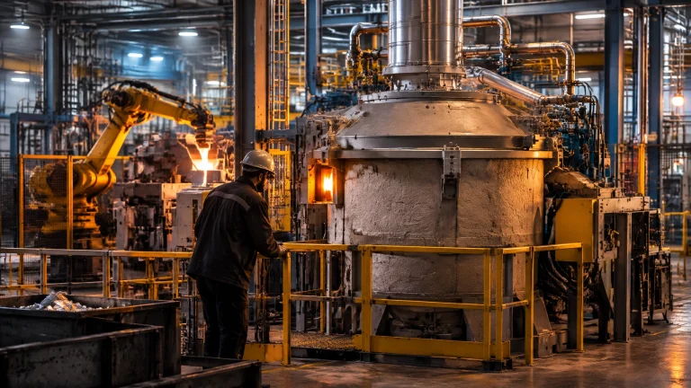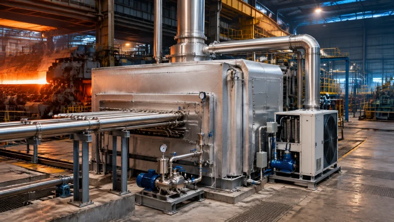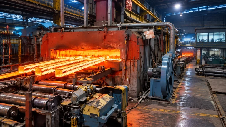
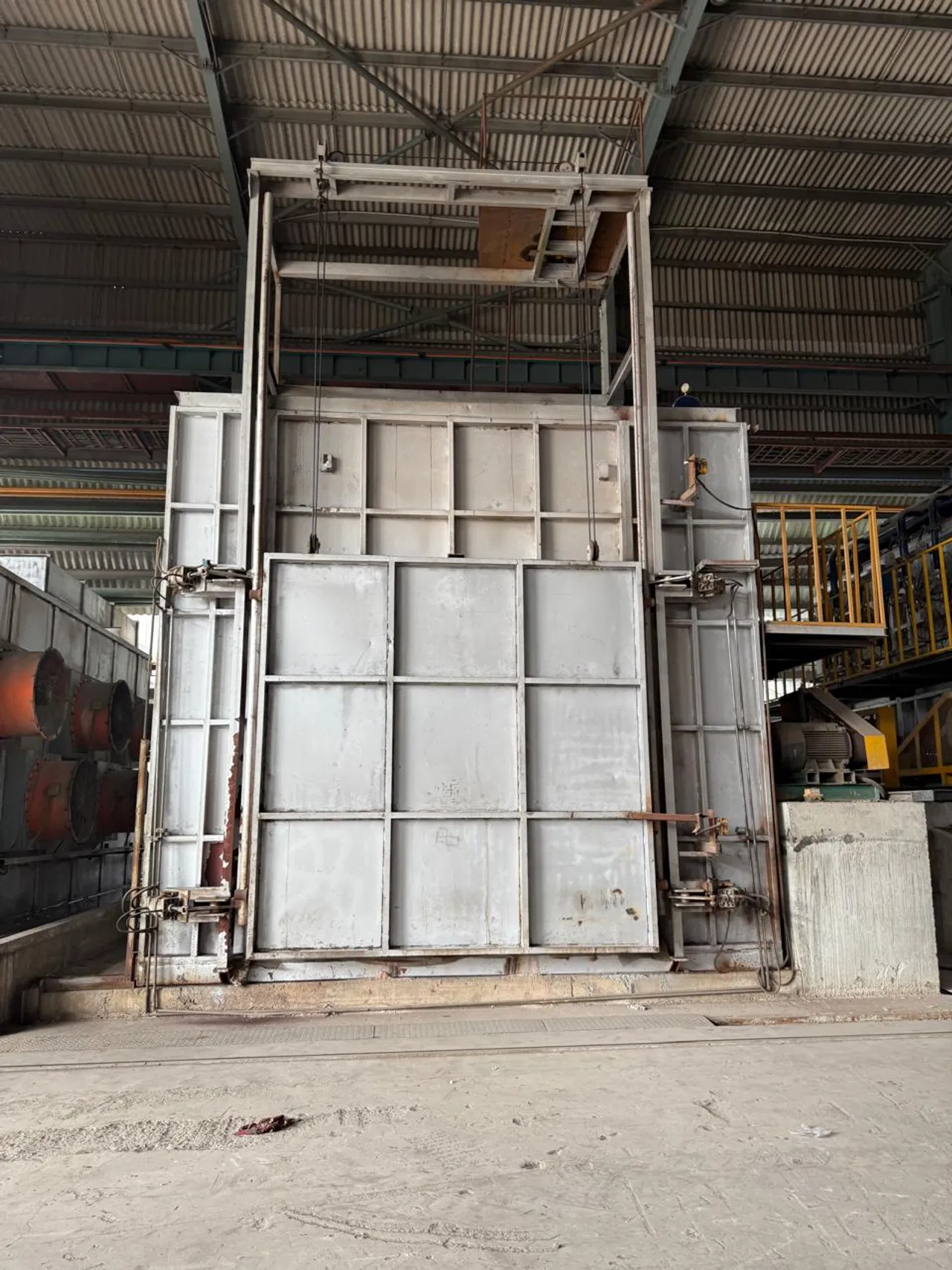
Furnace doors and seals occupy little space on a general arrangement drawing, yet they are among the most routinely overlooked paths for energy loss. A door is a machine, not simply an opening. Its frame, lifting mechanism, closure geometry, seals, operating sequence and interaction with furnace pressure all affect fuel use, product quality and safe throughput.
For a steel rolling mill, that may mean reheat-furnace charging and discharge doors. For batch heat treatment furnaces, it means disciplined door cycles between loads. The same engineering principles apply to melting and other thermal processing equipment.
Where the losses actually go
One door can contribute to three distinct heat-loss mechanisms:
-
Radiation through the opening. Hot surfaces radiate energy through the door opening. DOE guidance identifies furnace temperature, effective opening area and the fraction of time the opening is open as the main factors. Radiation increases sharply with absolute temperature, approximately with the fourth power. Above about 1,000°F, it becomes significant; the heat-flux scale rises from roughly 10,000 Btu/(hr·ft²) around 2,000°F-class temperatures to 100,000 Btu/(hr·ft²) or more near 3,000°F. These are approximate published reference scales, not design guarantees.[1]
-
Hot-gas escape. During charging or discharge, furnace gases can flow directly out through the opening. The amount depends on the opening profile, operating conditions and pressure at the door.
-
Cold-air infiltration. Natural draft or induced draft can create negative pressure, pulling ambient air through gaps at the door, frame or hearth. That air must be heated before it leaves through the exhaust system, consuming fuel. Infiltration can also increase metal oxidation and affect surface quality.[2]
A visible hot spot or gap is not just a local defect: it can signal an ongoing cost to energy efficiency, yield and product consistency.

Quantifying the door you already have
DOE’s practical radiation estimate is:
Radiation loss ≈ black-body heat flux at furnace temperature × effective opening area × open-time fraction
Effective area is not necessarily the opening’s measured face area. Wall thickness and opening aspect ratio reduce the area through which radiation can escape. DOE’s published graphs agree with detailed view-factor calculations within about 5%.[1] For a cycling door, calculate the open-time fraction as door-open time divided by the loading cycle. A fixed gap is effectively open continuously.
A stopwatch audit makes the estimate useful to operations. For each door, record the time it begins opening, reaches its required clearance, remains open, closes and seats. Log cycle frequency, load size and any time the door is left partially open. Compare typical and worst-case cycles. Oversized loads and avoidable dwell time deserve particular attention.
Radiation is only part of the picture. In one published walking-beam reheat-furnace case, door-opening losses, radiation plus convection, were reported at around 19% of total fuel input. The convective component exceeded the radiative component in that specific study; it is a case result, not a universal benchmark.[3] Separately, DOE states that leakage in a poorly maintained high-temperature furnace can increase fuel consumption by as much as about 10% of fuel input. That is a published upper-end reference, not a predicted saving for every repair.[2]
DOE’s illustrative forging-furnace example shows why small gaps merit attention: a 36-square-inch door opening in a 2,300°F furnace operating 6,000 hours per year was estimated to admit about 15,300 ft³/hr of air. At the example’s US-published fuel price of $8/MMBtu, it represented about $100,875 per year in wasted fuel for a 20 MMBtu/hr furnace.[2] These figures describe that example and its assumptions, not an estimate for another plant.
Seal engineering: fit, flexibility and geometry
The right closure system depends on temperature, cycling, door movement and the opening’s job.
- Braided ceramic-fibre ropes and tadpole gaskets provide compliant sealing at door perimeters and seating surfaces.
- Woven ceramic textiles and tapes accommodate cyclic thermal-mechanical movement where a flexible barrier is required.
- Ceramic strip, textile or chain curtains suit continuous-charge openings where a conventional door would obstruct production.
- Tunnel-like extensions reduce the effective opening; a shallow incline can direct radiation toward the insulation or incoming work.
- Radiation shields made from alloy sheet or ceramic board can help cover fixed openings. Sight glasses should have a damper or slide valve when not in use.[1]
DOE reports that flexible curtains generally reduce opening heat loss by about half while also reducing infiltration. Treat this as a published reference, not a guaranteed site result.[1] Examples range from a strip curtain at a reheat furnace to an aluminum melting furnace well door, a hot dip galvanizing plant preheat or zenith door, and charging openings on a metal recycling furnace or melting furnace for steel. Wire and cable industry annealing lines also benefit from attention to door and seal fit.
Comparing practical interventions
Benefits below are indicative. Actual results depend on furnace condition, duty cycle, geometry and commissioning.
| Intervention | What it addresses | Indicative benefit | Relative capex | Best fit | Principal failure mode |
|---|---|---|---|---|---|
| Ceramic-fibre rope or tadpole seal replacement | Perimeter leakage and imperfect seating | Restores closure; potential to reduce infiltration where seals are worn | Low | Batch doors and frames with damaged or compressed seals | Incorrect sizing, wear or poor seating |
| Strip/chain curtain or textile barrier | Radiation and air exchange at open charging points | Curtains generally reduce opening heat loss by about half per DOE reference | Medium | Continuous lines and frequent access openings | Degradation, gaps or poor tension |
| Tunnel extension or screen wall | Effective opening and direct radiant line of sight | Reduces exposed opening; site-specific | Medium | Fixed or continuous openings | Poor geometry or interference with the load |
| Automated door operation with pressure-control interlock | Excessive open time and leakage during cycles | Limits avoidable dwell; sealing plus suitable pressure control can address leakage losses reported up to about 10% of fuel input in poorly maintained furnaces, not a guaranteed saving | High | Repetitive cycles where controls and safe sequencing can be integrated | Poor interlock logic, sensor faults or over-pressurization |
Risks and engineering safeguards
An energy upgrade must preserve mechanical reliability and worker safety.
- Inspect curtains regularly; degraded strips and chains need tensioning or replacement.
- Specify seals that compress as intended without binding the door or adding mechanical stress to its lifting system.
- Do not over-pressurize the furnace. Excessive positive pressure can push hot gas through openings and create a worker hazard. DOE describes pressure control maintaining balanced, slightly positive pressure, often measured in hundredths of an inch, at major leakage points, where the furnace design permits it.[2]
- Set charging windows that reduce open time without compromising throughput, handling clearances or safe work practices.
- Check door-frame refractory and any water-cooled frame for integrity, not just the replaceable gasket.
- Interlock door position with burner and pressure-control sequences, and verify the response during commissioning.

A five-phase improvement roadmap
- Audit door and seal losses. Log open time per cycle; survey door travel, visible gaps and draft at likely leak points.
- Quantify and rank. Use the DOE effective-area and open-time method for radiation, then assess infiltration separately. Rank doors by operating hours, cycle frequency and condition.
- Pilot one door. Trial a suitable seal repair, curtain or geometry change, with door and pressure interlocks where appropriate.
- Measure and verify. Compare fuel intensity per unit of production before and after under comparable operating conditions. Track quality indicators, including oxidation where relevant.
- Institutionalize maintenance. Add closure checks to planned maintenance and track seal life, door alignment, actuator condition and repeat repairs.
Keep the closure system serviceable
A closure upgrade is only durable if the relevant spares are available when needed. Consider holding appropriate ceramic-fibre seal ropes and tadpole gaskets, curtain strips or chains, door lifting and actuation components, sight-glass dampers, and draft-gauge or pressure-sensor kits.
Continental Furnaces supports customers with furnace spare parts and prompt service designed to help minimize downtime. Our broader heat treatment furnace solutions and melting furnaces and recycling projects are part of customized industrial furnace systems engineered around operating requirements, not one-size-fits-all assumptions.
Build closure integrity into your efficiency plan
A sound door-and-seal program brings mechanical discipline and thermal performance into the same engineering decision. As an industrial furnace manufacturer with 35+ years of expertise, ISO-certified quality, customized solutions and super prompt service, Continental Furnaces works with customers to evaluate closure systems across their lifecycle.
Bring us your furnace type, operating cycle and door concerns. Request a consultation or quote and take a practical step toward sustained competitive advantage.
References
- U.S. Department of Energy, Reduce Radiation Losses from Heating Equipment, Process Heating Tip Sheet #7, January 2006. Read the reference
- U.S. Department of Energy, Reduce Air Infiltration in Furnaces, Process Heating Tip Sheet #5, January 2006. Read the reference
- Ameel et al., Determining heat losses in a reheat furnace: a case study, ECOS 2017, Ghent University. View publication record
- Thermal Analysis of an Industrial Furnace, Energies, 9(10), 833 (2016). Read the article
- U.S. DOE Industrial Technologies Program, Waste Heat Reduction and Recovery for Improving Furnace Efficiency, Productivity, and Emissions Performance, Technical Brief ITP-35876. Read the brief