Furnaces are calibrated, probes are replaced and heating records are reviewed. Yet the quench tank can run for years on operator habit. Hardness and distortion complaints may persist after furnace-side fixes because the bath has drifted in temperature, chemistry, agitation or cleanliness. In many plants, it is the least-instrumented step in the process, and a critical process asset in its own right.
All numerical figures below are indicative benchmarks drawn from published surveys, technical articles, standards and supplier references. They vary by plant, alloy, load, line type, throughput and local regulation. Supplier specifications and applicable customer and regulatory requirements govern.
Why the Bath Decides the Metallurgy
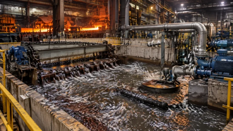
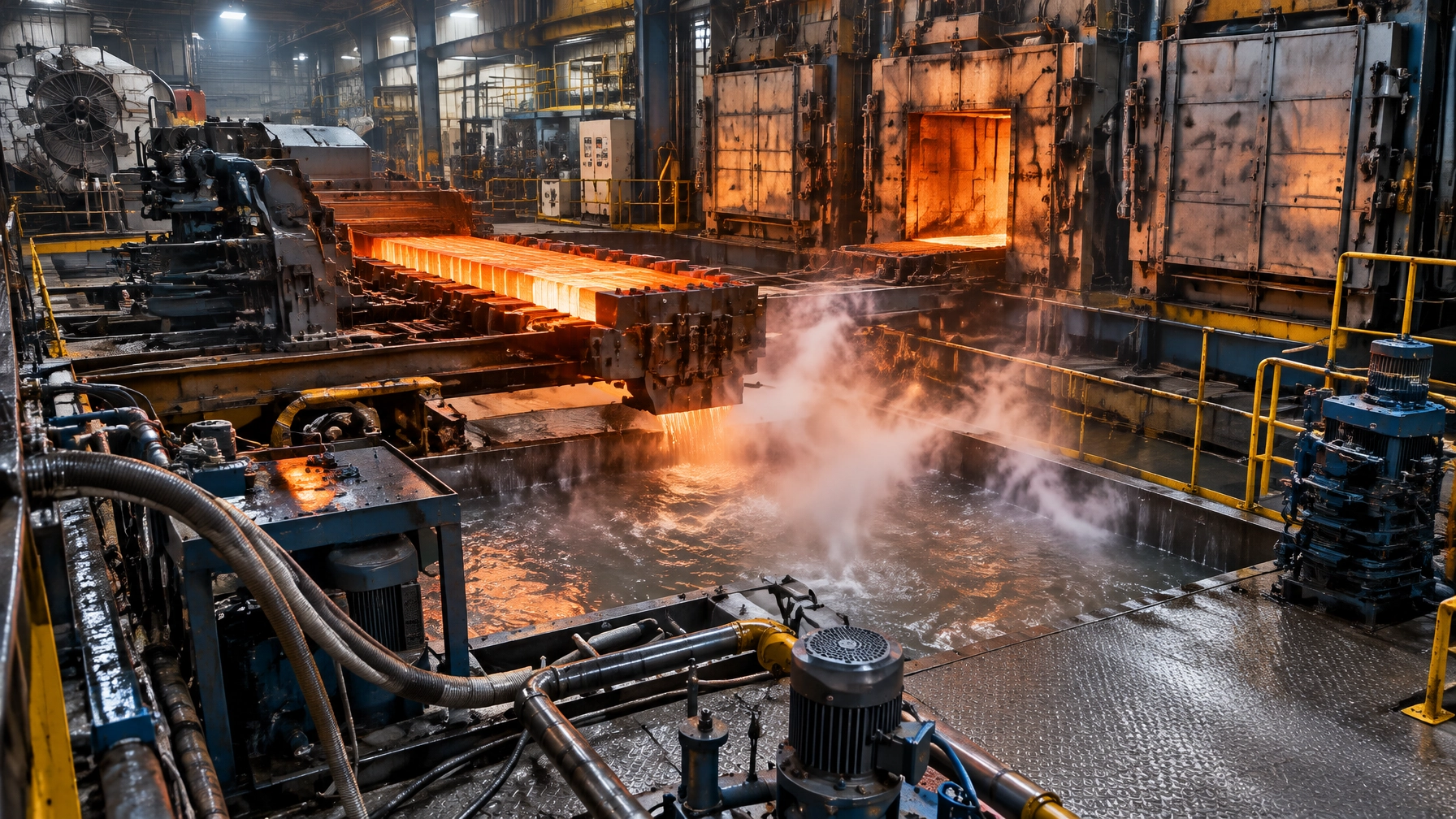
Liquid quenching progresses through a vapour blanket, nucleate boiling and convection stage. The nucleate-boiling region is typically the fastest heat-transfer stage and a major influence on distortion. Practical oil heat-transfer coefficients are often cited around 1,000–2,500 W/m²·K, with peak values of approximately 4,000–6,000 W/m²·K in the boiling range; cooling rates may exceed 100°C/s.
For many non-marquench oils, a working temperature window is approximately 50–65°C (120–150°F). Marquench oils may operate around 82–116°C (180–240°F), depending on the product. A rule of thumb is about one gallon of oil per pound of steel in the load; smaller baths demand particularly effective agitation. Flow design matters: draft tubes, down-pumping, entrance flares, anti-cavitation vanes and correct impeller submergence all help establish uniform cooling. Interlock heater elements with agitation to prevent local overheating.
For applications using heat treatment furnaces, qualify oil type, temperature, flow and load together, not as separate settings.
Table 1. Indicative quench oil classes and operating windows
| Oil class | Indicative GM Quench-O-Meter (nickel-ball) speed, seconds | Typical bath operating window | Typical duty |
|---|---|---|---|
| Fast oil | 8–10 | 120–150°F / 50–65°C | Low-hardenability alloys; carburised and carbonitrided parts; large cross-sections |
| Medium oil | 11–14 | 120–150°F / 50–65°C | Medium- to high-hardenability steels |
| Slow oil | 15–20 | 120–150°F / 50–65°C | High-hardenability steels where slower cooling limits distortion |
| Marquench / hot oil | 18–25 | 180–240°F / 82–116°C, product-dependent | Interrupted quenching; distortion-critical parts |
Different references quote slightly different class boundaries. The quenchant supplier’s product data and qualified process specification govern.
The Water Problem: One Gallon of Trouble
Water in hot quench oil is first a safety hazard, then a quality problem. A gallon of water flashing to steam can expand to roughly 1,600 times its liquid volume near atmospheric pressure, displacing oil that may be ejected onto hot surfaces or flames. This is a recognised mechanism behind serious quench-oil fires.
Possible ingress routes include water-cooled bearings, fans, doors and heat-exchanger tubes, as well as exposed or unclean totes, rain, fire-suppression leaks and maintenance errors. Make a daily Gemba leak walk part of bath control.
Indicative thresholds deserve cautious interpretation: oil saturation is commonly placed near 0.1% (1,000 ppm), while quench behaviour and viscosity changes may begin above roughly 200 ppm. A hot-plate crackle test is qualitative and can miss water below saturation. Use laboratory Karl Fischer titration (ASTM D6304) or distillation (ASTM D95) for confirmation. Automated detectors with typical sensitivity around 0.2–0.5% are backup alarms, not substitutes for routine sampling, tank-level checks and appearance checks.
Water can raise viscosity, prolong the vapour blanket, increase quench severity and make cooling uneven. Follow supplier guidance for separation, hot settling, vacuum degassing or centrifuging. Vacuum oil-quench systems are comparatively protected because evacuation can strip moisture from circulating oil.

Oil Health: The In-Use Test Panel
What Each Test Tells You
A complete panel turns bath condition into measurable process evidence:
- Viscosity (ASTM D445): rising viscosity can indicate oxidation or thermal breakdown and hinder heat transfer; falling viscosity can flag contamination.
- Total acid number (TAN): a rise tracks oxidation and may coincide with higher maximum cooling rates and increased cracking or distortion risk.
- Flash point (ASTM D92): a working rule is to keep the minimum flash point about 90°C (160°F) above operating oil temperature.
- Water: assess with a suitable quantitative method, not crackle testing alone.
- Suspended solids / precipitation number (ASTM D91): sludge can plug filters, foul heat exchangers, cause overheating and disrupt heat transfer.
- Cooling curve (ASTM D6200 or ISO 9950): the test that shows the cooling pathway and its drift with degradation or contamination.
- Additives: ICP spectroscopy (ASTM D4951/D6595) can help quantify depletion of cooling-rate accelerators. Nitrogen blanketing can reduce oxidation and sludge formation on hot-oil tanks.
Plot viscosity and cooling-curve parameters over time, then correlate them with hardness and distortion outcomes.
A Symptom-to-Action Table
Table 2. In-use quenchant symptom → what it means → first corrective action
| Symptom | What it may mean | First corrective action |
|---|---|---|
| Sudden flash-point drop or positive crackle test | Water ingress | Find the leak, confirm with Karl Fischer, and stand or degas the tank before running loads |
| Rising viscosity and TAN together | Oil oxidation or polymerisation | Check cooler performance and bath setpoint; plan partial refresh and consider nitrogen blanketing |
| Falling viscosity | Lower-viscosity oil or solvent contamination | Trace the source, sample and test |
| Cooling-curve maximum rate rising with TAN | Oxidation shifting quench severity | Re-verify hardening results, tighten temperature control and plan an oil change |
| Sludge, high precipitation number or fouled surfaces | Degradation products | Filter or centrifuge, inspect the exchanger and review agitation for local overheating |
| Soft spots without a furnace-side cause | Uneven agitation or contamination | Verify draft-tube flow and filters; sample the bath |
Actions are indicative practice. Supplier guidance and applicable standards govern.
Polymer Baths: Concentration Is a Moving Target
Polyalkylene glycol (PAG) quenchants are widely used. Their inverse solubility means polymer can come out of solution at a cloud point around 70°C (160°F), coat the hot part and moderate cooling. This enables water-based fluid to deliver oil-like quench severity. Roughly 10–30% solutions can span water-like to oil-like cooling; greater concentration generally slows the quench.
Use a handheld refractometer, applying the product-specific correction factor. Dissolved minerals, coolants and emulsified oils can shift that factor, so periodically verify against a benchtop refractometer at 20°C and lab viscosity checks. Pump shearing and pyrolysis shorten polymer chains, reducing viscosity and shifting cooling towards faster, more severe quenching.
Tramp oil is a preventable contaminant: it can form films and emulsions, inhibit oxygen transfer and encourage anaerobic bacteria and the familiar “Monday morning odour” of hydrogen sulphide. Skim oils, maintain aerated circulation and watch for emulsified oil that slows cooling and risks soft spots or low case depth. Central-system filtration around 10–25 microns is a common economic range; individual induction-machine filters may span 2–50 microns.
For mixing, fill with water to about three-quarters capacity, then add concentrate slowly under agitation, never add concentrate first. CQI-9 practice calls for daily concentration checks and quenchant quenchability monitoring; supplier guidance may call for cooling-curve analysis, particularly as systems age, alongside periodic pH, viscosity and biological testing. Confirm the exact frequency against the governing edition and customer requirements.
The Audit Trail: CQI-9 and AMS2759 Quenchant Readiness
Under AIAG CQI-9, 4th Edition, Section 3.14, in-use oil testing at least every six months covers water, suspended solids, TAN, viscosity, flash point and cooling curve, with limits based on supplier requirements. Water-soluble polymers require concentration and quenchability testing; methods may include cooling curves, viscosity or titration.
SAE AMS2759, Rev G, Section 3.10.3, requires certificates of conformance for quenchant shipments. For in-use baths, it calls for a biannual cooling-rate test, comparing maximum cooling rate and temperature at that rate with supplier baselines and permitted deviations. Polymer certificates include neat pH and viscosity and values at 20% dilution by weight. Many suppliers recommend quarterly sampling to provide a compliance margin if a scheduled sample is missed.
Take representative samples with agitation running, from the same safe location, into clean, dry containers. Cap promptly before cooling can draw in condensation. Typical sample volumes range from 250 mL to 2 L, depending on the method. Accepted cooling-curve methods include ASTM D6200, ISO 9950, JIS K2242, ASTM D6482 and ASTM D6549, as applicable.
Quenchant records belong in the same quality story as furnace calibration: auditors tracing a hardness escape will follow the chain from furnace charts to quench-bath reports.
From Reactive Sampling to Predictive Quenchant Management
In-bath quench-intensity sensors, including the published Fluid Quench Sensor concept, measure heat extraction from a constant-power element in real time. This can reveal agitation loss or fluid drift before parts enter the tank. In-line refractometers and PLC-controlled dosing can hold polymer concentration within a tighter operating band. Trend curves alongside hardness and distortion data, and compliance paperwork becomes a predictive tool: measure the variable that drives the outcome, then close the loop.
The Quench-Bath Spare-Parts Program
A planned furnace spare parts programme should cover:
- Immersion heaters and protection tubes; agitator motors, shafts and seals.
- Pump seals and impellers; exchanger tube bundles and gaskets, with a leak-test plan.
- Filter media and canisters; level and temperature instrumentation.
- Refractometers and calibration supplies; water-detection instruments.
- Drum and tote handling equipment for safe oil transfers.
Annual maintenance commonly includes draining and filtering oil and checking convection fans and agitators. Hold filters, seals and media at min-max levels; manage long-lead heater bundles, exchanger tubes and motors through named-lead-time agreements.

2026 Technology and Market Updates
Digital Fluid Management Goes Mainstream
Automated fluid monitoring and dosing platforms signal a move from clipboard to dashboard. In December 2025, Quaker Houghton added hardware to its QH FLUID INTELLIGENCE platform, including FLUIDCONTROL XMS 100/200 systems for automated monitoring and control, while engineered-fluids vendor Kerun introduced its KR-QL online monitoring concept for real-time tracking of quenching fluid concentration, pH, conductivity and temperature. Expect concentration, temperature and condition data to increasingly join SCADA historian records, and vendor case studies in the automotive sector already report stabilised quenchant processes with such systems.
Cooling Curves as Contract Language
More customers treat maximum cooling rate and temperature at maximum rate as acceptance criteria, not merely advisory data. AMS2759-style baseline discipline reinforces the connection between bath health and contract compliance.
Chemistry and Bath-Life Economics
Lower-viscosity polymers are designed to shear and pyrolyse more gently, drag out less and remix more readily. Oil-side practice increasingly favours fine filtration and centrifuging to extend bath life as used-oil disposal costs rise. Adoption varies by region and sector.
What This Means Across Your Furnace Fleet
A steel rolling mill with an integrated quench-and-temper line depends on bath control as much as furnace control. A foundry using an aluminum melting furnace to feed T6 heat-treatment lines must manage polymer concentration drift. Customers of a melting furnace for steel or metal recycling furnace may face the same quenchant demands further down their supply chains.
A hot dip galvanizing plant also needs rigorous water management in downstream cooling systems, albeit with different chemistry. Continuous hardening and tempering lines serving the wire and cable industry require stable bath conditions for repeatable mechanical properties.
Plants running heat treatment alongside melting and recycling often share cooling-water, filtration and maintenance resources. Those disciplines transfer across the fleet. Whatever the portfolio of thermal processing equipment, the bath belongs in the scope of industrial furnace systems supported end to end by an experienced industrial furnace manufacturer.

A Four-Phase Quench-Bath Roadmap
- Assessment and planning (30–60 days): Sample every bath, establish a full-panel baseline, map water-ingress sources and verify agitation and interlocks.
- Instrumentation and cadence (one to two quarters): Add level, temperature and water monitoring; set quarterly lab sampling; correct refractometer factors; document CQI-9/AMS2759 alignment.
- Operating discipline (three to six months): Standardise daily checks, improve filtration or centrifuging, skim polymer-tank tramp oil and link trends to hardness and distortion.
- Predictive and capital planning (six to eighteen months): Evaluate quench-intensity sensors, automated dosing and nitrogen blanketing; plan tank or exchanger renewal and consolidate spares.
Build Quench-Bath Reliability into an Enduring Partnership
Continental Furnaces brings 35+ years of expertise, ISO-certified quality and prompt service to thermal processing equipment, from supply and commissioning to after-sales support and spares. Request a quote or consultation to discuss furnace and bath-side engineering as part of an enduring partnership for sustained competitive advantage.
References
- The Herring Group, “Oil Quenching”
- The Herring Group, “Maintenance Practices, Procedures and Tips”
- The Herring Group, “Identifying Sources of Oil Quench Fires”
- G. Steiger & M. Bennett, “Heat Treater vs. Water: Best Practices to Avoid Water Contamination”
- G. Steiger & K. Kuroda, “The Selection, Care, and Maintenance of a Polymer Quenchant”
- M. Bennett & G. Steiger, “Quench Oil Management: AMS2759 & CQI-9”
- G.M. Webster, G.E. Totten & D.A. Wachter, “Quenchant Fundamentals: Condition Monitoring of Quench Oils”
- ASTM D6200 standard page
- AIAG CQI-9 Special Process: Heat-Treat System Assessment
- Quaker Houghton fluid-management automation announcement
- Kerun KR-QL quench fluid management
- Fuchs, “Quenchants Monitoring & Maintenance”