The water loop is the hidden half of the mill
Descaling water is often treated as a utility stream to clean up after production. That misses its role as a mill reliability input. Solids carryover, oil accumulation and unstable filtration can clog strainers and nozzles, interrupt rolling, and disturb the water delivery that supports consistent cooling.
The scale pit is therefore more than a settling basin. It is the first stage in a process circuit linking water quality, descaling performance, maintenance workload and the value of recovered iron units. For a steel rolling mill, reliable operation depends on managing that circuit as deliberately as the mill’s mechanical and thermal systems.
The scale of water use makes the opportunity significant: Nippon Steel reports approximately 190 tonnes of water per tonne of steel across the industry’s varied uses, mostly cooling, with much of it recirculated.[1] These are published reference values, not universal requirements; verify against your own line data, adopted standards and jurisdiction. The same disciplined approach applies to water systems associated with heat treatment furnaces, while recognizing that indirect cooling circuits have different service conditions.
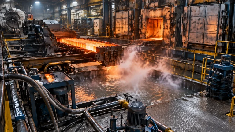
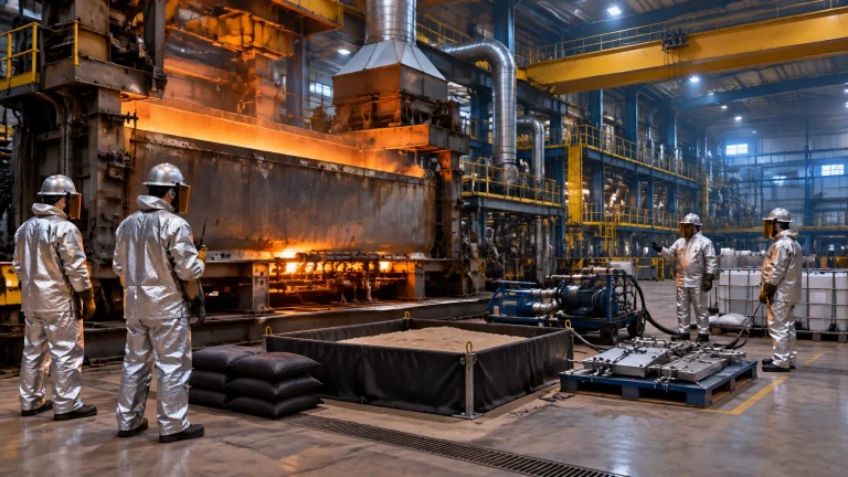
Illustrative image: a high-pressure descaling header directing water onto hot steel.
Where the solids and oil come from
Descale sprays dislodge iron oxide from hot steel. Roll cooling and caster sprays add flow, while hydraulic leaks can introduce oil rapidly into a collection system. Nippon Steel describes direct-cooling water from continuous casting and rolling as carrying scale and rolling oil through the scale sluice to the pit.[1] WesTech also notes that a caster hydraulic-line failure can send a large quantity of fluid into the wastewater collection system.[2]
Published guidance gives broad example ranges of 100–5,000 mg/L suspended solids and 5–200 mg/L oil and grease in descale-water influent.[4] Actual concentrations vary with product, line conditions, water balance and upset events. Sample both normal operation and representative peaks before selecting treatment equipment or setting chemical controls.
Scale-pit engineering: retention, solids and oil
The pit’s primary role is to separate coarse material and provide a manageable hydraulic buffer. Nippon Steel describes a conventional split around 100 μm: particles at or above that size are commonly removed by pit settling, with finer solids handled downstream.[1] Other references discuss gravity settling of granular scale above roughly 200–250 μm. These cut points describe typical process behavior, not guaranteed capture sizes; particle shape, density, flow distribution and turbulence matter.
WesTech cites 30–45 minutes as typical scale-pit retention guidance for continuous-caster service.[2] Use it as a preliminary reference, not a substitute for sizing against actual peak flow, solids load, usable pit volume and cleaning arrangements.
Oil skimming must be coordinated with solids removal. Nippon Steel reports that much of the circulating oil attaches to particulate surfaces, so oil removal often improves when solids capture improves.[1] Free-floating rolling or hydraulic oil still requires a skimmer and a route for collection. Keep the water surface calm enough for separation, avoid short-circuiting flow, and inspect skimmer performance after changes in production or oil loading.
A published Nippon Steel continuous-caster case offers a useful example, not a guarantee. After applying its NCST chemical approach to help fine particles adhere to coarse grains and settle in the pit, treated-water suspended solids fell from 19 to 6 mg/L and oil from 7 to 1 mg/L. The plant’s historical supply-water criteria were SS ≤20 mg/L and oil ≤5 mg/L.[1]
Choosing the right separation stage
Each unit operation has a distinct duty. A robust train uses the pit for coarse solids and free oil, then adds downstream treatment to meet the line’s water-quality target.
| Technology | Primary duty | Typical capture role | Footprint / maintenance | Watch-outs |
|---|---|---|---|---|
| Scale pit | Settle coarse scale; skim free oil | Coarse solids, commonly around 100 μm and larger in cited guidance | Large civil footprint; scraper and periodic cleanout required | Poor flow distribution or inadequate retention can carry solids forward |
| Lamella clarifier | Settle fine suspended solids | Finer particles after coarse-scale removal | More compact than conventional settling basins; requires sludge removal | Published surface-loading references of 1.0–2.5 m/h need local verification; fine solids may require lower rates to limit re-entrainment |
| Deep-bed filter | Polish residual solids and coalesce remaining oil | Fine particulates and residual oil | Moderate footprint; backwash and media care required | Rising differential pressure, poor backwash or solids overload reduce performance |
| Hydrocyclone | Separate coarse, dense particles | Coarse scale where particle density and size allow separation | Compact; no settling basin, but wear and pressure-drop monitoring matter | Not a replacement for fine-solids filtration or free-oil skimming |
Lamella loading rates and other numerical design references in this article are published reference values, not universal requirements; verify against your own line data, adopted standards and jurisdiction.[4]
Spray-nozzle reliability: pressure is only one variable
Descaling impact depends on pressure and flow, but also on nozzle geometry, spray angle, standoff distance and jet distribution. Excessive overlap can form a water-cushion layer that reduces impact; inadequate overlap leaves stripes of scale that may be rolled into the product. Edge-drop width must be matched to the spray pattern, and worn nozzles can shift the impact profile.
A Lechler vendor case study at TKS Bochum reported that nozzle-type and spray-height changes increased impact by approximately 35% in roughing and 60% in finishing, without increasing pressure or total flow. The case also reported a 55% reduction in rolled-in-scale downgrades over 1992–1999.[3] These are results from a specific published audit, not a forecast for another mill. The practical lesson is to audit spray patterns and nozzle condition before assuming that higher pump pressure is the answer.
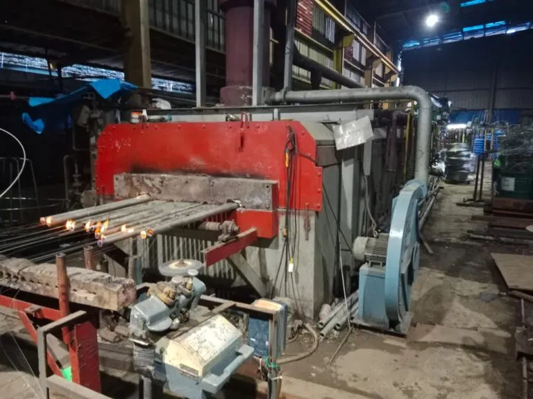
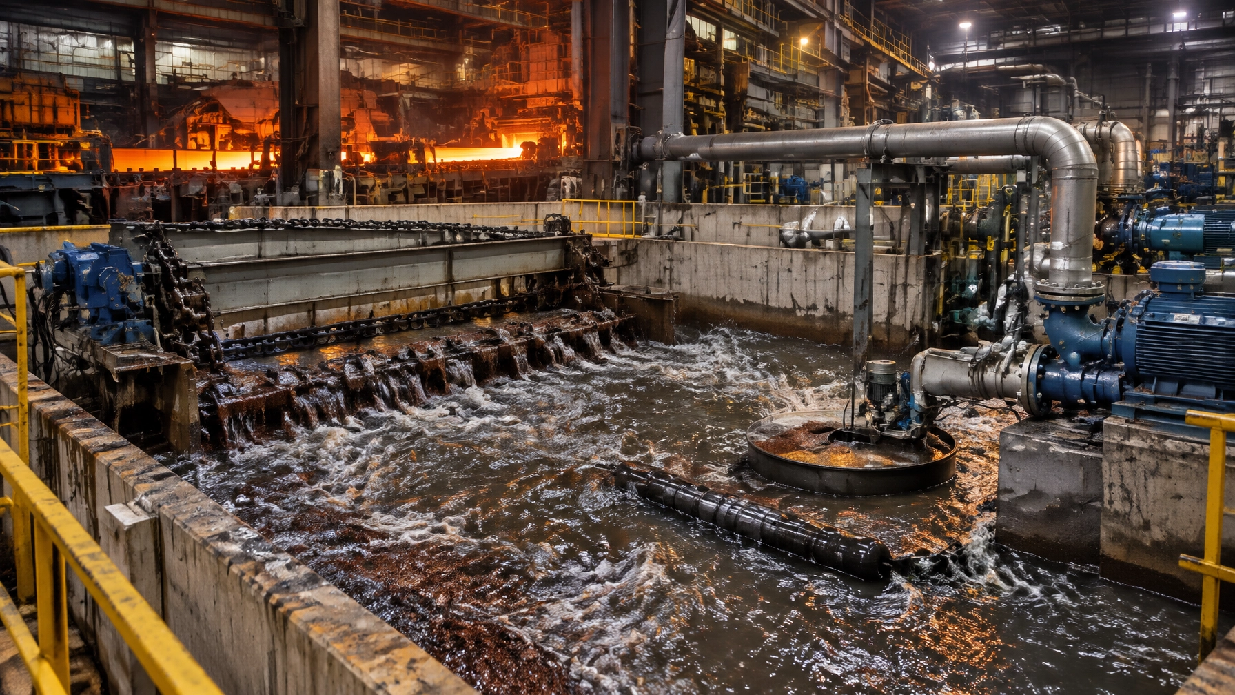
Illustrative image: filtration equipment in a steel-plant utility area.
Filtration trains, sludge handling and regulatory readiness
A common treatment sequence is scale pit → clarification or decanting → deep-bed filtration → cooling and recirculation. Depending on the water and plant requirements, the train may also include hydrocyclones, chemical-assisted settling in the pit, or legacy electromagnetic filters. Published polymer doses for fine-solids coagulation are on the order of 0.5–3 mg/L, but dose selection requires jar testing and operating validation.[4]
Plan backwash and sludge handling as part of the water circuit, not as a separate disposal problem. Deep-bed-filter backwash can be routed to a thickener and then a filter press; clarified overflow and pressate can return to the scale-pit circuit where water quality and local rules permit.[2] Track filter differential pressure as an operating KPI alongside flow, turbidity or suspended solids, and oil.
WesTech describes possible tighter US iron-and-steel effluent limits for metals including nickel, chromium, lead and zinc as a regulatory outlook.[2] This is not a statement of requirements in every jurisdiction: confirm current rules, permit conditions and discharge limits with the relevant local authority.
Mill-scale recovery: from captured solids to iron units
Mill scale commonly contains 65–72% iron, often in a mix of wüstite, magnetite and hematite. Recovery can support a circular-economy strategy, but value depends on scale quality, contamination, moisture and local markets.
Sintering is one established route. Literature discusses moderate additions around 40–50 kg per tonne of sinter or approximately 11% of the mix, with bed permeability a key constraint.[5] Oily scale complicates sintering and may favor briquetting or other agglomeration routes for approved BOF or blast-furnace feed. In a meltshop, recovered iron units should be assessed against the plant’s approved feed routes, not assumed to be suitable for direct charge to a melting furnace for steel. Economics vary with local scrap and mill-scale prices, processing cost and product specifications.
Keep water circuits distinct where process chemistry differs: a hot dip galvanizing plant has its own water-quality considerations, while rinse water in the wire and cable industry presents a different contamination profile. Foundry circuits associated with an aluminum melting furnace also require their own process-specific handling. Continental Furnaces, an industrial furnace manufacturer, considers these interfaces as part of broader industrial furnace systems and thermal processing equipment planning; a metal recycling furnace route for recovered material is a separate process decision from water-loop design.
Phased roadmap for a reliable recirculation loop
- Audit and sample the loop. Map water flows, pit volume, solids and oil at multiple operating points. Record interruptions, nozzle blockages and filter pressure trends.
- Stabilize solids and oil capture. Check inlet distribution, pit retention, scraper coverage and skimmer operation. Confirm where fine solids and attached oil are being removed.
- Remediate headers and nozzles. Measure pressure and flow, verify spray overlap and edge coverage, then inspect wear and alignment.
- Close the water balance and sludge logistics. Review backwash flows, thickener capacity, filter-press operation, recycle quality and the destination of each residual stream.
- Select a scale-recovery route. Characterize iron content, oil, moisture and particle size; then compare suitable recovery options against local handling costs and market requirements.
Keep the recirculation loop healthy before you need it
Plan critical furnace spare parts and water-loop wear items against inspection findings and lead times. A practical list includes:
- Descale nozzles and tungsten-carbide wear parts
- Strainers and filter media
- Skimmer chains, blades and scrapers
- Scale-pit clarifier rake components
- Pump wear rings and seals
- Differential-pressure gauges
Maintain a documented inspection schedule and reorder thresholds. Review Continental Furnaces’ spares and accessories as part of a wider maintenance plan; the correct scope depends on the actual equipment installed.
The recirculation loop is an enduring reliability partnership between production, maintenance and water treatment. Continental Furnaces brings 35+ years of expertise, ISO-certified quality, customized solutions and super prompt service to industrial process planning. Consult our team to assess your water-loop priorities and identify a practical path to sustained competitive advantage: request a consultation.
References
- Nippon Steel & Sumitomo Metal Technical Report No. 115 (2017), “High Efficient Solid-liquid Separation Technology.” Link
- WesTech Engineering, “Metals & Steel Wastewater Treatment Solutions.” Link
- Lechler GmbH, “Audits of existing hydro mechanical descaling systems in hot rolling mills as a method to enhance product quality.” Link
- Degrémont-SUEZ Water Handbook, “The steel industry: open recirculating systems.” Link
- “Recycling of steel plant mill scale via iron ore sintering.” Link