Every figure quoted is an indicative benchmark drawn from published conference papers, plant technical reports and supplier technical literature. Actual values vary with mill type and configuration, stand position, motor rating and control scheme, spindle design and misalignment angle, roll diameter and crown, gearbox ratio and tooth geometry, lubricant grade, filtration and water ingress, duty cycle, and inspection and overhaul practice.
A mill driveline has no graceful degradation path. A worn component elsewhere in a mill may give time for intervention; a failed spindle, pinion or torque limiter stops the mill instantly and takes production with it. Yet drivelines are often measured by whether they have broken, rather than by the condition of the parts that decide when they will.
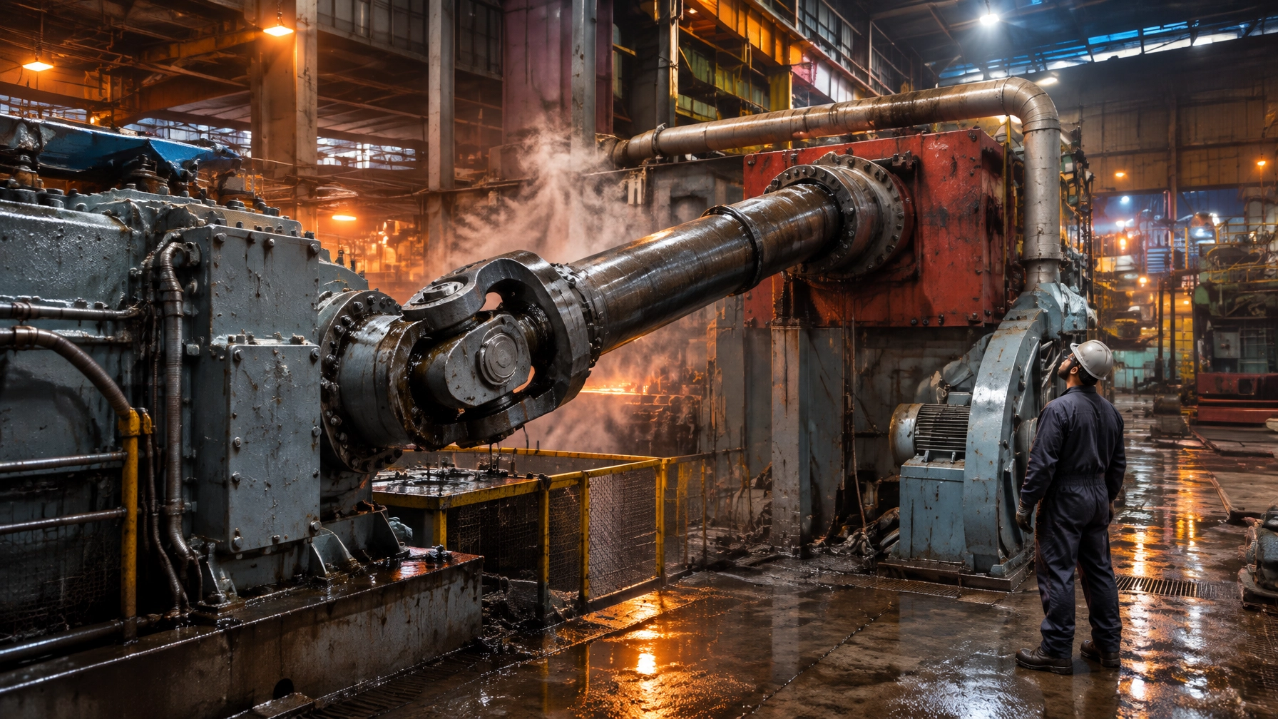
The chain is explicit: motor, torque limiter or safety coupling, motor-end spindle joint, spindle shaft, roll-end spindle joint, roll hub, pinion stand or reduction gearbox, work and back-up rolls. The failure that matters is not necessarily the one with the longest history, but the one with the shortest warning. A driveline gives years of small signals and then minutes of consequence. Many plants can report the diameter of every work roll, but cannot report the release torque of the coupling protecting the drive train, the water content of the gearbox oil, or the actual peak torque seen by the shaft. The driveline needs to be auditable on the same terms as the roll shop and the furnace.
What the drive train is, and where it actually fails
Each component has a distinct role and failure signature:
- Roll-end universal joint or slipper bearings: torque spikes and coolant ingress accelerate wear.
- Gear spindle teeth: sliding wear increases backlash and can reduce torque capacity.
- Torque limiter: friction-disc wear, contamination or an inconsistent rebuild can shift the release setting.
- Pinion stand teeth: pitting and case distress develop under repeated loaded contact.
- Gearbox oil: water and particulate contamination shorten component life, even when the system appears to be operating normally.
- Motor: winding thermal duty and bearing currents affect electrical and mechanical reliability.
Four signals commonly precede driveline failure:
- Rising torque amplification.
- Growing backlash or runout.
- Oil cleanliness drifting off target.
- Oil or sump temperature creeping upward without a change in duty.
Spindle architecture is a life-cycle-cost decision, not a purchasing one
A spindle selection shapes maintenance frequency, lubricant use, energy loss, product stability and the consequences of torque spikes. The trade-offs between slipper joints, gear spindles and universal joint shafts are set out in Paluh, Hills and Wojtkowski’s rolling-mill selection paper and Grawenhof’s comparison of drive-shaft concepts.
Table 1. Slipper, gear and universal joint spindles compared
| Spindle type | Misalignment capability and backlash | Lubrication and maintenance burden | Efficiency and life-cycle position |
|---|---|---|---|
| Slipper spindle | Same kinematics as a Cardan joint. Bronze or non-metallic slipper elements wear through loaded sliding contact. Excessive inherent tolerances reduce concentricity and can contribute to mill chatter. | Lubricant is not contained and may need to be supplied continuously. | Sliding friction and wear affect efficiency and maintenance demand. |
| Gear spindle | Crowned gear teeth; roughly 6 degrees of misalignment capability. Torque capacity falls as misalignment increases because fewer teeth share the load. Design backlash is 0.020 to 0.100 in and grows with wear. Runout of 0.020 to 0.060 in can result from heat-treatment distortion. | Weekly lubrication is recommended for optimum life; contaminated grease is expelled as the spindle wears. | Established design, but sliding wear, backlash growth and lubrication work affect lifecycle cost. |
| Universal joint shaft | Cross and roller bearings; misalignment capability of 15 degrees or more. Typically under 0.003 in backlash, which does not increase until complete bearing failure. Virtually no radial runout. | Monthly relubrication is typical. | Torque capacity is not significantly influenced by operating angle. Life expectancy is 3 to 6 times that of gear spindles at 1.5 to 1.8 times the initial cost. |

On a seven-stand finishing mill, lubrication labour and clean-up alone can outweigh the initial price difference. The comparison below uses the published example figures from the universal-joint selection paper.
Table 2. What spindle choice costs in lubricant, man-hours and clean-up on a seven-stand finishing mill
| Coupling type | Lubrications per year per stand | Lubrication man-hours per year across seven stands | Lubricant plus clean-up cost per year |
|---|---|---|---|
| Gear spindle | 48 | 3 man-hours per stand; 1,008 hours total; about USD 80,640 labour at USD 80 per hour | About USD 13,440 lubricant plus USD 57,600 clean-up; about USD 71,040 total |
| U-joint | 12 | 1 man-hour per stand; 84 hours total; about USD 6,720 labour | About USD 168 lubricant plus USD 720 clean-up; about USD 888 total |
Energy loss is another lifecycle cost. At Kawasaki Steel’s Mizushima Works, replacing slipper joints with universal joints produced measured power savings on the F2 stand. Theoretical slipper-joint efficiency fell from about 99.15% at 2 degrees to 97.44% at 6 degrees with a friction coefficient of 0.1, and to 93.61% at 6 degrees with a coefficient of 0.25. The universal joint remained above 99.9% across the reported comparison range. Measured savings were 47% during idling at 60 rpm, with power falling from 340 kW to 180 kW; 3.4% during rolling; and 5.7% overall. The study reports that hot strip mills accounted for 19% to 29% of total works power consumption at Mizushima. A mechanical efficiency loss of this scale is therefore an energy cost, not merely a maintenance line item. See Inoue, Kaneko and Iizima’s study.
Size selection is equally consequential. In a reversing rougher or Steckel mill, the roll-end joint is often limited by the work-roll discard diameter. If a 900 mm joint is needed but the discard diameter is 850 mm, the joint is built at 850 mm and carries a shorter bearing life. Motor-end joints can be sized separately; where they are, bearing replacement intervals of 36 to 60 months are possible against 12 to 24 months at the roll end.
Torque peaks, not average torque, decide when a driveline ends
The torque amplification factor (TAF) is the ratio of torque measured by a strain gauge on the spindle to the torque theoretically produced by the motor. It is always above unity. A tight, well-maintained and properly operated mill typically records 1.1 to 1.4; some passes in poorly maintained or badly operated mills exceed 1.7. These ranges are described in Paluh, Hills and Wojtkowski’s selection paper.
A reversing mill motor rated at 8,000 to 10,000 hp, with a current limit of 220% to 250% of nameplate, can produce 1.5 million ft-lb at current limit and torque spikes above 2.0 million ft-lb. Those peaks pass through a joint whose swing diameter must fit within the work-roll discard diameter.
The bending moment matters too. At 3,165,000 in-lb and 2.25 degrees, a gear spindle generated about 508,000 in-lb of bending moment, against 124,000 in-lb for a universal joint, roughly four times as much. A gear spindle adds friction and load displacement to the torque term. That bending moment loads the roll neck and chock bearings twice per revolution. The comparison is published in Paluh, Hills and Wojtkowski’s paper.
Driveline torque has often been treated as evenly distributed along the shaft, with higher natural frequencies considered insignificant. However, simulation and case studies on heavy plate mill drivelines show that stiffness, length, inertia distribution and the gradient of the incoming torque peak combine to shift torque levels substantially. The motor control system can work with or against that behaviour. These dynamics are explored in Bergstrom, Myrgren, Jesus and Miazzo’s study.
Rolling torque is usually back-calculated from motor current, but the drive chain damps that signal. Strain gauges installed on ArcelorMittal Tubarão’s roughing mill drive shafts showed actual torque peaks and their dynamics, supporting residual-life estimation. The measurement approach is detailed in Santos et al. and in Jesus, Fieweger, Bastian and Miazzo’s process-monitoring paper. If you do not know your TAF, you do not know whether your spindles are being consumed at design rate or twice it. No overhaul interval can then be correct.
The torque limiter is protection only if its setpoint is still true
A friction or shear-type safety coupling sits between motor and spindle to release the driveline before the spindle, pinion or motor is damaged. At SSAB Oxelösund, two Voith SafeSet couplings protect the heavy plate mill drivelines. One, an SR-F 1000 with a maximum torque of 10,000 kNm, is mounted between the universal joint shaft and motor. In a decade, the couplings released twice, both times immediately and precisely, preventing serious damage. SSAB keeps a spare coupling in stock to avoid making restart dependent on repair. Details are in Voith’s SSAB case study.
At Columbus Steel’s plate mill, a scheduled 2012 intervention combined a full-scale torque test with an overhaul of the safety couplings to re-establish the optimum release setting. The case is documented by Westberg, Nordström, Hidaka and Miazzo. A friction coupling’s release torque is a mechanical fact that can change with disc wear, contamination and rebuild quality. It can drift high and cease protecting the drive train, or drift low and release on a legitimate bite, stopping the mill unnecessarily. Both conditions can look normal from the control room.
Newer digital-mechanical limiters provide calibrated setting indication, record setting changes, alarm on a faulty setting and signal when release frequency calls for inspection. Treat release torque as a controlled parameter with a value, date, method and owner, like a furnace setpoint. The maintenance case for scheduled torque verification is also set out in Myrgren, Miazzo and Weisbjerg.
Table 3. Protection layers on a mill drive train and what each one really protects
| Layer | What it protects | How it is verified | How it fails quietly |
|---|---|---|---|
| Torque limiting coupling | Spindle, pinion stand and motor from overload and shock | Torque test or calibrated release check at overhaul | Release torque drifts with disc wear and rebuild quality |
| Spindle and its joints | The rest of the drive train from misalignment and bending loads | Backlash and runout measurement, bearing inspection at change-out | Wear first appears as growing backlash and product quality loss, not a stoppage |
| Pinion stand and reduction gearbox | Torque multiplication and speed match to the rolls | Tooth contact pattern, backlash, oil analysis and vibration | Pitting and case distress progress under normal-looking oil temperature |
| Drive motor | Conversion of electrical to mechanical power within thermal limits | Winding temperature, insulation resistance, bearing current survey | Thermal duty creeps up with harder product mix and clogged cooling |
| Control and rolling schedule | The magnitude and gradient of every torque peak the layers above must survive | Torque traces and TAF trending | Schedules get harder without anyone re-checking the driveline |

Gearbox oil is a condition signal you are sampling too rarely
A BHP Steel assessment of 66 critical machines found 82% of oil samples outside targeted cleanliness levels. The audit estimated potential system-wide savings of up to USD 30 million per year in material and repair costs for lubricated components, excluding downtime. The findings and case data are presented in Ding’s BHP Steel lubrication assessment.
At the hot strip mill, a tilt-table gearbox was one of 25 gear units on a centralised system. Its average life was 14 months, with replacement and shutdown costs reaching USD 125,000 a year. Better sealing against scale and water, and harder gear surfaces, had not extended life. The sump sample contained 10 times the particle concentration and 28 times the water content of the central-system sample. That contamination could cut rolling-bearing life by 80% to 90%. Poor oil exchange between the gearbox and the central system was identified as the root cause; the target life was raised to an estimated 36 to 48 months.
At Newcastle’s no-twist finishing mill, the drive system included 63 gear sets, 99 rolling element bearings and 43 Clevite bearings operating above 12,000 rpm. Filtration was improved from coarser than 30 micron to 12 micron in 1986 and 6 micron in 1988. Clevite bearing failures fell from 12 in 1985 to 1 in 1988, while mill speed increased from 46 m/s to 120 m/s. This is a clear example of oil cleanliness supporting both speed and reliability.
Water needs to be measured, not judged by sight. SKF data cited by Shell indicates that 0.04% water, or 400 ppm, can reduce tapered roller-bearing fatigue life by up to 44% compared with dry oil. The maximum allowable water content for a No-Twist mill is 0.2%, below saturation at normal operating temperature, so damaging water may be invisible in a sight glass. The Shell high-speed wire-rod mill guidance describes a main-tank oil range of 49 to 54°C, with 60°C as the usual maximum for high-speed mill equipment. Oil should not be heated above 70°C, which promotes oxidation and thermal degradation. Filtration to ISO 18/16/13 or better is recommended for high-speed equipment, with ISO 17/15/12 for primary flushing.
At Corus Shotton’s five-stand tandem mill, 28,000 litres of ISO VG 460 oil measured ISO 22/19/16 against an 18/16/14 target. Continuous fine filtration brought it to 17/15/11 in under seven weeks, avoiding a replacement gearbox estimated at GBP 200,000. See the C.C. Jensen application study.
In a Hy-Pro case, a rolling mill reservoir with repeated bearing losses at about USD 30,000 each had water content of 29,000 ppm. Dehydration reduced it to 383 ppm within two weeks, with no bearing failure reported since. Another example showed ISO VG 460 oil at 133,000 ppm water falling to about 330 cSt, thinning the film and increasing metal-to-metal contact. The case is described by Edwards, Hoeg and Trent.
Temperature trend matters as well as the absolute value. AGMA places the gearbox sump-temperature limit below 200°F. Above 150°F, lubricant life can halve for every additional 18°F. Set an alarm on a change of roughly 50°F, as well as on the absolute limit. For temperature-trend context, see Machinery Lubrication’s hot-bearing guidance.
Table 4. What one oil report is telling you about the drive train
| Test or reading | What changed | Driveline element implicated | First action |
|---|---|---|---|
| ISO 4406 cleanliness code | Two or more codes above target | Any gearbox or pinion stand, and the filtration itself | Verify filter location and rating before adding filtration |
| Water content by Karl Fischer | Above 0.05% to 0.2%, depending on equipment | Seals, breathers, cooler tube leaks and washdown ingress | Find the ingress path, then dehydrate |
| Viscosity at 40°C | Outside ±10% of grade | Wrong top-up oil, shear, fuel or solvent ingress, or severe water | Confirm the grade actually delivered to that sump |
| Iron and alloying elements by ICP | Rising trend against the machine’s own baseline | Gear teeth, bearings or a worn coupling | Cut and inspect at the next opportunity rather than changing oil |
| PQ or ferrous debris index | Step change without a cleanliness step change | A local wear site, often a bearing or gear mesh | Narrow it with vibration on that gearbox |
| Varnish potential or MPC | Rising with normal cleanliness and temperature | Cooler running hot or sump over temperature | Treat oil, then fix heat and aeration |
Repair welding, rebuilding and the failure nobody writes a procedure for
A 2024 failure analysis of a hot rolling mill drive shaft found a crack initiated at a discontinuity in a weld-recovered region. The shaft was SF 60 grade, recovered by welding and then machined. Chemical composition and tensile results complied with specification, but metallography located the crack origin at the discontinuity. The lesson from Mudesto’s analysis is direct: restoring geometry and passing composition and tensile checks does not necessarily restore fatigue performance. The properties that matter may lie in the heat-affected zone, fusion boundary and residual stress field, not in the mill certificate.
The same acceptance logic applies to gear-tooth rebuilds, laser-clad surfaces and re-machined slipper faces. Acceptance criteria need the process record, not only the final dimension. Post-weld heat treatment (PWHT) and stress relief of a repaired shaft or gear body are furnace operations, and the chart is evidence of the cycle. Carburising and hardening a new pinion tell the same story at the start of its service life. A repair specification without a PWHT requirement, hardness traverse and NDT acceptance level is an instruction to find out later.
Laser cladding is used to rebuild continuous caster lateral rolls and restore gear flanks, and in-situ borided laser-cladding layers have been tested for gear repair. But a clad layer inherits the substrate and its prior heat treatment. Cladding a fatigued shaft body restores diameter, not fatigue life.
2026 technology and market updates
The market direction is toward measurable load, controlled lubrication and refurbishment quality that can be audited. These are not substitutes for sound engineering; they make its assumptions visible.

Oil-lubricated spindles are replacing grease as the default
North Star BlueScope replaced its original grease-lubricated spindles with oil-lubricated tube-type spindles to eliminate a recurring maintenance cost and downtime source, documenting the cost-benefit in its published case. Essar Algoma ordered Danieli DanJoint oil-lubricated gear spindles with integrated torque monitoring for heavily loaded hot strip mill stands F1, F2, F5 and F6; the first pair was installed in September 2017. Details appear in Donadon et al..
Voith and BUMA Engineering developed GearLink, commissioned at Voestalpine Grobblech in December 2013. It combines universal joints and gear couplings to fit a 1.35 times larger joint into the same space, with 2.5 times the torque capacity and a claimed 20 times longer lifetime. The design is described in Grawenhof’s GearLink paper. Continuous oil lubrication removes the grease route, clean-up and housekeeping burden, but adds an oil system that must itself be monitored. Many mills accept that trade.
Torque telemetry moves from a project to a channel
The strain-gauge installation at ArcelorMittal Tubarão demonstrated the value of measuring shaft torque directly. A condition-monitoring architecture can use spindle torque to schedule spindle maintenance and help optimise rolling schedules and roll-gap lubrication. Voith’s Acida line, low-cost IoT strain-gauge torque measurement demonstrated in 2025, and software-based digital observers estimating elastic torque from motor signals all support broader access to this measurement.
The trade-off is practical. A software observer is lower-cost and needs no battery, but inherits the damping and modelling error it was built to avoid. A shaft sensor measures directly, but needs a measurement window, a battery or inductive supply, and a cable-management plan.
Lubricant condition sensing goes online, and varnish becomes the metric
Inline water-saturation sensors can report percent relative humidity; online particle counting can catch cleanliness drift; varnish potential can indicate slow degradation that a quarterly water and viscosity panel misses. A quarterly sample cannot see a six-week seal failure. A sump gaining 2,000 ppm of water between samples has already consumed part of the bearing life the sampling programme was meant to protect.
Refurbishment quality becomes an auditable document
Acceptance is moving from dimension and hardness alone toward the weld procedure, PWHT chart, hardness traverse and NDT record. It is the same shift heat-treatment documentation has already made: a finished part is not fully qualified without evidence of how it was processed. The failure analysis above shows why that evidence matters.
What this means across your furnace and mill fleet
The driveline is not isolated from the rest of production. Its loads are shaped by incoming material, process schedules, lubrication practices and the metallurgy of its components.
- A steel rolling mill inherits its drive-train duty from the rolling schedule. Adding a harder grade or heavier coil without re-checking TAF quietly shortens spindle and pinion life. The audit should connect driveline records to the mill’s maintenance plan.
- Heat treatment furnaces support post-weld heat treatment and stress relief of repaired shafts, gear bodies and coupling components; the chart is the acceptance record. They also carburise, harden and temper pinions and gear wheels, where case depth and core hardness determine pitting resistance over years of service. This puts a heat treatment furnaces supplier inside the driveline reliability chain.
- An aluminum melting furnace and a melting furnace for steel influence melt quality and inclusion content. Those factors shape cast structure and, in turn, the rolling loads seen on the first passes.
- A metal recycling furnace handling remelted charge must account for residual and tramp elements that make mechanical properties scatter, so drive-train duty varies coil to coil.
- A hot dip galvanizing plant has continuous line drives, bridle and sink-roll drives, and tension control that keeps strip from slipping. Those systems require the same oil and grease discipline.
- Pickling plants combine line drives with a corrosion environment that can attack seals, breathers and coupling surfaces. An oil report may reveal the ingress after the route has already caused damage.
- In the wire and cable industry, rod-mill and drawing-machine drives operate at high speed on circulating oil, where water ingress and cleanliness dominate bearing life. The No-Twist mill case is a relevant example.
- Furnace spare parts and drive-train spares share a consumables discipline: coupling discs, seals, breathers, filter elements and oil need the same planning attention as grinding wheels and burner parts. Stocking a spare torque limiter is a decision with a real number attached. See furnace spares and accessories.
- Specify documented heat-treatment records with industrial furnace systems and require them from the industrial furnace manufacturer. The driveline is only as good as the metallurgy inside it. For operations using thermal processing equipment, process records make that connection auditable.
A four-phase roadmap to a drive train you can schedule
A steel rolling mill that can state the condition of its drive train can plan an outage. One that cannot is planning around the next failure. The sequence below moves from what you can see to what you can schedule.
Phase 1: Baseline and audit, 30 to 60 days
- Name every driveline element and record its last overhaul date.
- Record torque-limiter release torque and setting date.
- Pull oil-analysis history by gearbox and confirm samples came from the right location.
- Review spindle backlash and runout records.
- List every spindle, joint and coupling change over the last five years, including the cause.
- Record whether torque, TAF or spindle life is measured at all.
Phase 2: Restore the measurement, 1 to 2 quarters
- Set cleanliness and water targets for each gearbox; locate filtration and dehydration where ingress occurs.
- Sample at correct points using flushed valves and proper bottles.
- Make torque-limiter release checks scheduled and recorded tasks.
- Start measuring backlash and runout at every roll change on the worst stand.
- Trend sump temperature against duty rather than the calendar.
Phase 3: Instrument and schedule, 3 to 6 months
- Add torque measurement or a validated observer on the highest-consequence stand.
- Derive TAF by stand and pass, then use it to review the rolling schedule and torque-limit setting.
- Add online water-saturation and particle-count monitoring on main gearbox sumps.
- Replace calendar-based spindle overhauls with condition-based work where the data supports it.
Phase 4: Design and capital, 6 to 18 months
- Evaluate spindle architecture where the roll-end joint is diameter-limited.
- Consider oil-lubricated or hybrid spindle designs where grease is the cost driver.
- Specify torque limiters with calibrated setting indication.
- Put release-torque verification, oil-cleanliness targets, backlash limits and repair procedures, including PWHT, into every driveline and refurbishment purchase specification.
Phase 1 cannot be skipped. A release-torque verification programme without a baseline is a guess; a monitoring system installed before oil targets exist becomes another screen nobody reads. Phase 4 is where the capital is committed, but only a mill that has completed Phases 1 to 3 knows which element it is actually buying.
An enduring partnership in thermal engineering
Continental Furnaces brings 35+ years of experience, ISO-certified quality, customised solutions and prompt service. Our work sits on both sides of the thermal-processing problem: we build furnaces used to heat-treat the pinions, shafts and gear bodies inside a drive train, and support mills that consume them.
Explore our heat treatment furnaces, melting furnaces and recycling projects, pickling plants, hot dip galvanizing plant solutions and furnace spares and accessories. Request a quote for a drive-train and heat-treatment review. The objective is an enduring partnership built around lifecycle value and reduced downtime. A driveline you can schedule is a production asset; a driveline you cannot is a coin toss.
Technical references
- Paluh, Hills and Wojtkowski, Design and Selection of Universal Joints for Rolling Mills, Ameridrives: https://www.altraliterature.com/-/media/Files/Literature/article-reprints/ameridrives-power-transmission/p-7618-apt.ashx
- Inoue, Kaneko and Iizima, Power Saving in Hot Strip Mill Drives by Means of Universal Joints, ISIJ International 24(10), 1984: https://www.jstage.jst.go.jp/article/isijinternational1966/24/10/24_10_833/_pdf/-char/ja
- Grawenhof, Comparison of Rolling Mill Drive Shaft Concepts, ABM 52nd Rolling Seminar 2015: https://abmproceedings.com.br/en/article/comparison-of-rolling-mill-drive-shaft-concepts
- Grawenhof, GearLink, a Quantum Leap in Drive Technology for the Next Generation Heavy Plate Mills, ABM 2015: https://abmproceedings.com.br/en/article/download-pdf/gearlink-a-quantum-leap-in-drive-technology-for-the-next-generation-heavy-plate-mills
- Bergstrom, Myrgren, Jesus and Miazzo, Dynamic Effects and Torque Limitation in Heavy Plate Mill Drivelines, ABM 2011: https://abmproceedings.com.br/en/publications/proceedings-of-the-rolling-and-metal-forming-seminar/event/proceedings-of-the-rolling-and-metal-forming-seminar/article/dynamic-effects-and-torque-limitation-in-heavy-plate-mill-drivelines
- Jesus, Fieweger, Bastian and Miazzo, Process and Condition Monitoring at a Finishing Mill, ABM 2011: https://abmproceedings.com.br/en/article/process-and-condition-monitoring-at-a-finishing-mill
- Santos et al., Rolling Torque Determination Using Strain Gauges in ArcelorMittal Tubarao HSM Driving Shafts, ABM 2009: https://abmproceedings.com.br/en/article/determinao-dos-torques-de-laminao-atravs-do-uso-de-strain-gauges-nos-eixos-de-acionamento-do-ltq-arcelor-mittal-tubaro
- Westberg, Nordstrom and Hidaka, Columbus Steel, Correct Torque Limitation and Maintenance, ABM 2013: https://abmproceedings.com.br/en/article/columbus-steel-correct-torque-limitation-and-maintenance
- Myrgren, Miazzo and Weisbjerg, Correct Torque Limitation and Driveline Optimization, ABM 2012: https://abmproceedings.com.br/en/article/correct-torque-limitation-and-drivelineoptimization-5
- Voith, SSAB pushes the limits with Voith SafeSet couplings: https://www.voith.com/corp-en/VT_SuccessStory_SafeSet_SSAB_19_vvk_VT2487_en.pdf
- Hoffman, Sundermann, Knoblauch and Malan, Installation of Oil Lubricated Tube Spindles at North Star BlueScope Steel, ABM 2009: https://app.abmproceedings.com.br/en/publications/proceedings-of-the-rolling-and-metal-forming-seminar/event/proceedings-of-the-rolling-and-metal-forming-seminar/article/instalao-de-eixo-de-acionamento-tubular-lubrificado-a-leo-na-northstar-bluescope-steel
- Donadon et al., New DanJoint High Performance Oil Lubricated Gear Spindles for Essar Steel Algoma's DSPC, IRC 2019: https://abmproceedings.com.br/en/article/download-pdf/new-danjoint-high-performance-oil-lubricated-gear-spindles-for-essar-steel-algomas-dspc
- Ding, An Integrated Approach to Lubrication Excellence at BHP Steel: https://www.machinerylubrication.com/Read/42/bhp-steel-lubrication
- Cao and Guerzoni, Tackling High-Speed Wire Rod Mill Circulating-Oil Challenges Head On, Shell: https://www.shell.com/business-customers/lubricants-for-business/sector-expertise/metals/equipment-maintenance/_jcr_content/root/main/section/simple/promo_1145218101/links/item0.stream/1750353205533/43ecdc2e5cafa6d385aa478f7b1f4408fc71d322/hite-paper-on-tackling-high-speed-wire-mill-circulating-oil-challenges-head-on-new-look-and-feel.pdf
- C.C. Jensen, Gear Oil, Steel Strip Rolling Mill, application study at Corus Shotton: https://www.cjc.dk/fileadmin/root/File_Admin_Filter/doc_Customer_Cases/Industry_GearOil_SteelStripRollingMill_ASIN5040UK.pdf
- Edwards, Hoeg and Trent, Improving Rolling Mill Lube Oil Performance and Useful Life, Hy-Pro Filtration: https://maintenanceworld.com/wp-content/uploads/2013/07/Improving-Rolling-Mill-Lube-Oil-Performanc.pdf
- Mudesto, Failure Analysis of Hot Rolling Mill Drive Shaft, ABM 2024: https://abmproceedings.com.br/en/article/failure-analysis-of-hot-rolling-mill-drive-shaft
- Riddell, How to Manage Hot Bearings in Your Plant, Machinery Lubrication: https://www.machinerylubrication.com/Read/30608/manage-hot-bearings