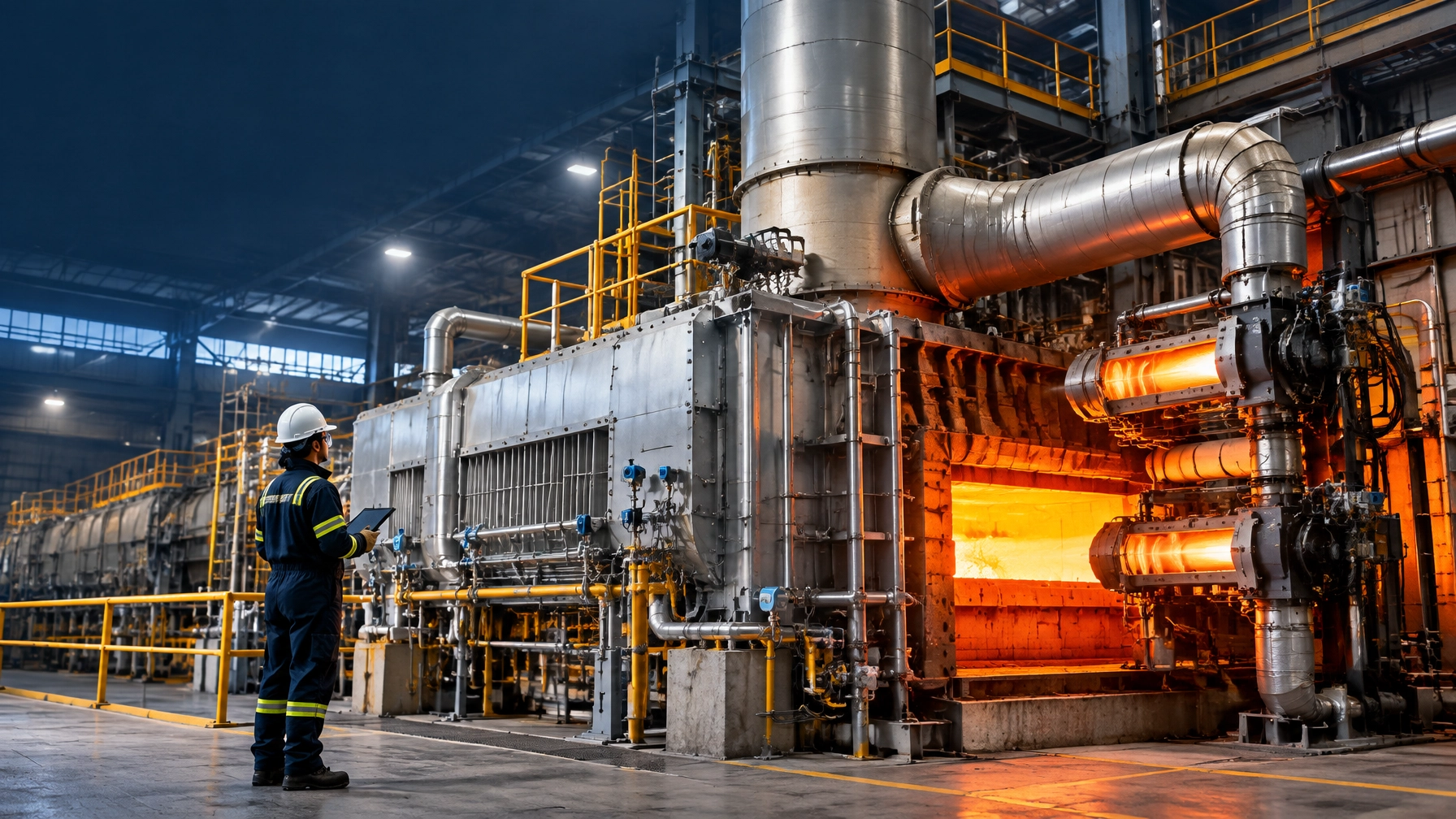
Industrial furnaces routinely discharge valuable energy through hot flue gases. In many fired systems, 20–50% of the original energy input can leave as waste heat, particularly through exhaust gases, heated products, radiation and cooling systems. For plant heads and energy managers, this is not merely an environmental issue. It is a direct profitability, yield and competitiveness issue.
The 2026 priority is clear: recover high-quality exhaust heat, convert it into combustion-air preheat or useful process heat, and maintain the recovery assets so performance does not deteriorate after commissioning.
For a steel rolling mill, heat-treatment line, aluminum melting furnace, metal recycling furnace or hot dip galvanizing plant, the most effective architecture combines:
- Recuperative burners or external recuperators
- Regenerative burners with ceramic heat-storage media
- Flue-gas economizers, waste-heat boilers or process-air preheaters
- Stable combustion controls and variable-speed exhaust systems
- Inspection access, bypass arrangements and serviceable furnace spare parts
- Measurement of flue temperature, oxygen, pressure drop and recovered energy
Why waste heat recovery is an essential 2026 upgrade
The U.S. Department of Energy waste heat recovery report identifies three conditions for a viable project:
- An accessible and sufficiently hot waste-heat source
- A correctly selected recovery technology
- A reliable end-use for the recovered energy
For industrial furnace systems, combustion-air preheating is usually the first and most economical end-use. The exhaust transfers energy to incoming combustion air, reducing the fuel required to reach the same furnace temperature.
DOE engineering benchmarks show that combustion-air preheat can produce approximately 10–30% fuel savings, with higher reductions possible in high-temperature applications where the exhaust stream is clean, continuous and properly controlled.
Typical screening targets for 2026 projects include:
- Exit flue-gas temperature before recovery: 800–1,200°C for high-temperature melting and reheating duties
- Final flue-gas temperature after recovery: approximately 150–300°C, subject to dew-point and corrosion limits
- Combustion-air preheat: 400–800°C, depending on equipment design and materials
- Fuel reduction: 15–30% for well-matched systems
- Recuperator heat-exchange effectiveness: 80–90% when clean and correctly sized
- Typical retrofit payback: 12–36 months for high-utilization continuous furnaces
These figures are engineering benchmarks, not universal guarantees. The actual result depends on operating hours, exhaust composition, production rate, fuel price, excess air, pressure drop and maintenance discipline.
Recuperators versus regenerative burners
A recuperator is a continuous gas-to-gas heat exchanger. Hot flue gas passes on one side while combustion air flows on the other. The two streams remain separated, which makes the technology suitable for many heat treatment furnaces, reheat furnaces and melting systems.
A regenerative burner system uses paired burners and ceramic media. One burner fires while its partner exhausts through a hot ceramic bed. The bed stores heat and then releases it to incoming combustion air when the flow direction reverses.

| Parameter | Traditional cold-air firing | Recuperative system | Regenerative burner system |
|---|---|---|---|
| Combustion air temperature | 25–40°C | 400–650°C typical | 500–800°C possible |
| Fuel consumption | Baseline | 10–25% lower | 15–30% lower |
| Flue-gas heat recovery | Minimal | Continuous exchanger recovery | Cyclic ceramic-media recovery |
| Mechanical complexity | Low | Moderate | High |
| Pressure-drop sensitivity | Low | Moderate | High |
| Best application | Low-duty or intermittent furnaces | Heat treatment, melting and reheat | High-duty continuous furnaces |
| Indicative payback | Not applicable | 12–24 months | 18–36 months |
| Maintenance requirement | Conventional burner service | Exchanger cleaning and inspection | Valve sequencing, media and burner maintenance |
When a recuperator is the correct choice
A recuperator is usually the strongest retrofit option when:
- The furnace operates at a steady load
- Exhaust gas is relatively clean
- Available space is limited
- The plant requires a simpler flow arrangement
- The process operates continuously but does not justify regenerative complexity
- The project must minimize production interruption
When regenerative burners deliver the greater return
Regenerative systems become more attractive when:
- Furnace duty is high and continuous
- Exhaust temperatures remain above approximately 900°C
- The plant requires maximum combustion-air preheat
- Fuel costs and annual operating hours are high
- The furnace has multiple zones and stable burner sequencing is possible
The design must also address NOx formation. Very high combustion-air preheat increases flame temperature. Low-NOx burner geometry, staged combustion, oxygen-trim control and correct excess-air management are therefore integral, not optional, parts of the project.
Application benchmarks across thermal processing equipment
Heat treatment furnaces
Heat-treatment exhaust commonly falls within the medium-temperature recovery range of approximately 430–650°C. Recuperative burners, radiant-tube heat recovery and secondary air preheating can reduce fuel demand while improving ramp stability.
For batch and continuous systems, the target is not simply lower gas consumption. The recovery design must preserve:
- Temperature uniformity
- Atmosphere integrity
- Metallurgical repeatability
- Quench or cooling sequence
- Loading and unloading productivity
A relevant Heat Treat Today case study reported a 53% reduction in ramp cycle time and a 59% reduction in gas consumption per load after combining waste-heat recovery with combustion monitoring. That result illustrates the value of treating heat recovery, burner tuning and process control as one engineering program.
Explore Continental Furnaces’ heat treatment furnaces for customized batch and continuous thermal-processing solutions.
Steel rolling mill and reheat furnace operations
A steel rolling mill can lose substantial energy through billets, slabs and reheat-furnace exhaust. Typical furnace exhaust temperatures may reach 900–1,050°C before recovery, while a properly designed recuperator can raise combustion-air temperature to approximately 500–650°C.
The expected operational benefits include:
- 15–25% fuel reduction
- Lower stack losses
- Faster heat-up and recovery after charging
- Improved zone-to-zone balance
- Reduced specific energy consumption per tonne
- Lower carbon intensity per tonne of rolled product
In CCR and CCM-linked operations, the recovery system must be designed around actual casting and rolling schedules. A mismatch between furnace discharge, caster availability and rolling demand can reduce utilization and weaken payback.
Aluminum melting furnace and metal recycling furnace systems
Secondary aluminum melting produces high-temperature exhaust, often approximately 1,090–1,200°C at the furnace outlet. The DOE has documented cases where preheating combustion air to approximately 480°C reduced fuel use by roughly 29%.
However, aluminum recycling presents specific engineering risks:
- Chloride and fluoride attack from fluxing
- Dross and particulate fouling
- Secondary combustion of volatile contaminants
- Thermal shock during charging
- Overheating during process transients
A bypass damper, dilution-air strategy, accessible cleaning sections and corrosion-resistant materials are essential. Continental Furnaces’ melting furnaces and recycling projects address the wider circular-economy requirement: recover metal value while reducing the energy intensity of remelting.
Hot dip galvanizing plants and the wire and cable industry
In a hot dip galvanizing plant, the strongest waste-heat opportunity normally lies in the annealing, preheating and combustion sections rather than direct recovery into the zinc bath. Recovered heat can preheat combustion air, drying air or suitable process streams.
For galvanizing and wire-processing lines, the 2026 design target is typically:
- Flue-gas recovery from annealing sections
- Combustion-air preheat of 400–600°C where appropriate
- 15–25% fuel reduction
- Stable strip or wire temperature before coating
- No compromise to coating thickness, surface quality or line speed
The integration of pickling plants with galvanizing and wire lines also matters. Cleaner upstream surfaces reduce process contamination and protect downstream heat-recovery assets from aggressive deposits.
Maintenance strategy: preserve the recovered energy
A heat-recovery system that is not maintained becomes an expensive obstruction. Fouling increases pressure drop, reduces heat transfer and forces burners to operate with additional fuel.

Weekly and shift-level checks
- Record flue-gas temperature before and after the recovery device
- Check combustion-air temperature and fan load
- Review oxygen and carbon-monoxide readings
- Confirm damper and bypass positions
- Listen for valve leakage, vibration or abnormal burner noise
Monthly checks
- Inspect exchanger surfaces for dust, dross and scale
- Trend differential pressure across the recuperator or regenerator
- Verify thermocouple and pressure-transmitter calibration
- Inspect expansion joints, refractory blocks and access doors
- Check burner flame pattern and ignition reliability
Planned shutdown checks
- Clean heat-transfer surfaces according to fouling rate
- Inspect ceramic media for cracking, plugging or deformation
- Test automatic reversing valves and actuator timing
- Verify fan capacity against original design values
- Replace degraded seals, gaskets and burner components
- Revalidate flue-gas dew-point and minimum stack-temperature protection
A practical performance rule is simple: investigate immediately when recovered-air temperature falls by 10% or pressure drop rises by 15% from the commissioning baseline. These changes usually indicate fouling, leakage, exchanger damage or combustion imbalance.
Continental Furnaces supports lifecycle reliability through furnace spares and accessories, including burners, sensors, seals, refractory components, controls and other critical parts.
The 2026 implementation roadmap
Phase 1: Assessment and planning
- Establish baseline fuel consumption in Nm³/t, kWh/t or GJ/t
- Measure exhaust temperature, flow, oxygen and pressure
- Map operating hours and production variability
- Identify the highest-value end-use for recovered heat
- Check structural space, duct routing and fan capacity
Phase 2: Technology selection
- Select a recuperator for moderate complexity and continuous heat exchange
- Select regenerative burners for high-duty, high-temperature operation
- Specify corrosion-resistant materials for aluminum and chemically active exhaust
- Include bypasses, inspection doors and cleaning access
- Model NOx, pressure drop and combustion-air temperature
Phase 3: Installation and commissioning
- Install during a planned shutdown
- Balance burners zone by zone
- Confirm safe purge, flame supervision and valve sequencing
- Record the new baseline at different production rates
- Validate product quality and thermal uniformity before declaring savings
Phase 4: Performance assurance
- Track specific energy consumption monthly
- Compare actual recovery against the design heat balance
- Schedule cleaning based on measured degradation
- Maintain a critical inventory of recovery-system spares
- Review payback using actual fuel prices and uptime
The strategic conclusion
Waste heat recovery is a quantum leap in furnace economics when it is engineered around the complete process rather than added as an isolated heat exchanger. Recuperators deliver practical, retrofit-ready savings. Regenerative burners provide higher air preheat and stronger performance for demanding continuous operations. Both require disciplined maintenance, accurate measurement and a clear end-use for recovered energy.
As an experienced industrial furnace manufacturer, Continental Furnaces brings more than 35 years of engineering expertise to heat treatment, melting, recycling, galvanizing, pickling and integrated industrial furnace systems.
Begin with a furnace energy audit and a measured flue-gas profile. Contact Continental Furnaces to convert wasted thermal energy into lower specific consumption, higher yield and sustained competitive advantage.