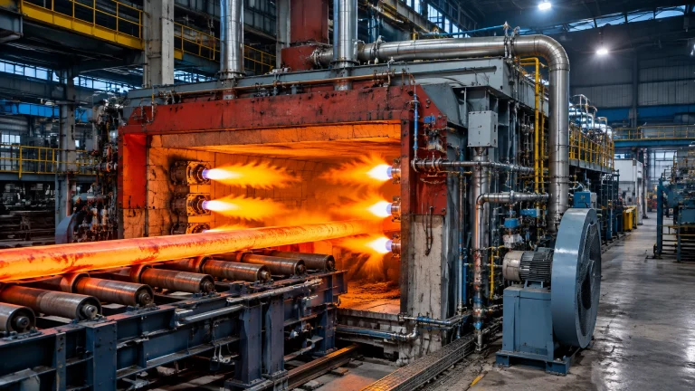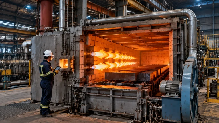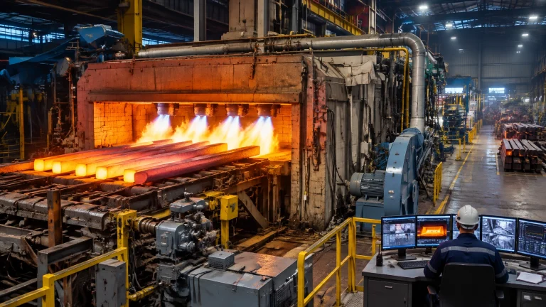
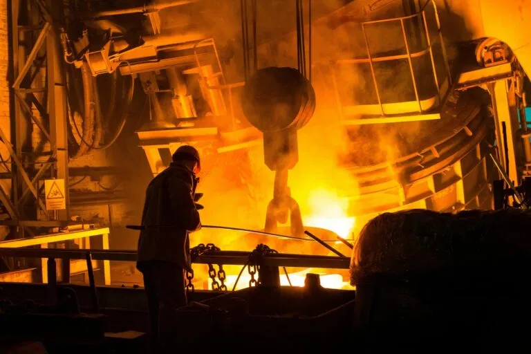
The furnace room is now an electrical-engineering challenge as much as a thermal one. Induction power supplies, DC arc rectifiers and variable-frequency-drive (VFD) handling equipment make melting shops among the most demanding loads connected to an industrial grid. Their effects (harmonic distortion, resonance and voltage flicker) can reduce equipment life, disrupt controls and complicate utility compliance.
For a reliable melting furnace for steel or other metals, power quality must be assessed across the installation, at the point of common coupling (PCC), and under representative operating conditions, not inferred from a single equipment rating.
What a melting shop does to a clean sine wave
Rectifiers and other power-electronic converters draw current in pulses rather than as a smooth sinusoidal waveform. Those pulses create harmonic currents. As they flow through the impedance of transformers, cables and the utility network, they can distort the voltage waveform seen by the facility and other connected users.
Typical rectifier signatures include:
- Six-pulse rectifiers: characteristic 5th and 7th harmonic currents.
- Twelve-pulse configurations: phase-shifted supplies are designed to cancel much of the 5th and 7th, leaving the 11th and 13th as dominant characteristic orders. Real performance depends on transformer matching, load balance and operating conditions.
Induction furnaces and AC arc furnaces are nonlinear loads, but their power-quality behavior differs. An induction furnace’s converter can inject substantial harmonics; large ramp-ups can also create voltage changes. An arc furnace is particularly challenging because its arc makes the load unbalanced and rapidly time-varying, producing harmonics and flicker. Research on AC arc furnaces documents these combined power-quality effects and the need for measurements under actual operating conditions.[^1]

Where harmonics bite: the equipment you already own
Harmonic currents add heating and electrical stress to components designed around fundamental-frequency power. The consequences are operational as well as technical:
- Transformers: harmonic heating can require derating; in severe cases, reported derating can reach up to 50%, particularly in high-distortion conditions such as THD above roughly 15%. This is not a universal threshold or a fixed derating rule: actual capacity depends on the transformer design, spectrum and loading.
- Motors: reference guidance reports efficiency loss of about 0.1% for each 1% of voltage distortion; excessive harmonic heating can reduce motor life by up to 50%. These are indicative effects, not guarantees for every motor or duty cycle.[^2]
- Capacitor banks: harmonic current raises capacitor stress and can lead to overheating, dielectric failure or premature replacement.
- Neutrals: in three-phase, four-wire systems, triplen harmonics, especially the 3rd and 9th, can add in the neutral. Under certain load conditions, neutral current can reach approximately 175% of phase current, creating an overload risk.
- Protection and controls: harmonic distortion and electrical disturbances can contribute to nuisance trips or cause instrumentation and PLC signals to behave unpredictably.
Why capacitor-bank resonance matters
Power-factor-correction (PFC) capacitors interact with the inductance of the supply system. Together, they can form a resonant circuit. If that resonant frequency is close to a harmonic produced by a furnace or drive, the system may amplify the harmonic instead of suppressing it. Symptoms reported in foundry case studies include transformer overheating, breaker trips and capacitor-bank failures.[^3]
Detuned PFC banks use series reactors to shift the resonance point away from problematic harmonic orders. Tuned filters can also provide a low-impedance path for selected harmonics, but their design must account for the full system impedance and changing operating configurations. Installing capacitors or filters without a resonance study can make conditions worse.
IEEE 519-2022: the rules your utility actually enforces
IEEE 519-2022 sets steady-state harmonic distortion goals at the PCC. It does not apply the same limits automatically to every internal furnace bus. For PCC voltage distortion, the standard specifies:
- Up to 1.0 kV: 8.0% total harmonic distortion (THD); 5.0% maximum individual harmonic.
- 1 kV to 69 kV: 5.0% THD; 3.0% maximum individual harmonic.
The responsibility is shared: users control harmonic current emissions within applicable limits, while utilities manage system impedance so voltage distortion remains within the standard’s goals. The required current limits depend on factors including the short-circuit current to demand current ratio; there is no single universal current-THD percentage for every plant.[^4]
A measurement campaign should establish the PCC with the utility, then use Class A power-quality meters for at least one week during full, representative production. Record voltage and current harmonics, events and operating states, including furnace cycles and mill-drive operation. Compare current distortion using TDD (total demand distortion), referenced to maximum demand current, rather than treating instantaneous THDi as the compliance metric.
Flicker is a separate assessment from IEEE 519 harmonic limits. AC arc furnaces are a classic flicker source. SVCs and STATCOMs provide dynamic reactive-power compensation, but neither guarantees compliance by itself: flicker severity depends on grid short-circuit strength, and published EPRI findings include an EAF case where an SVC did not fully mitigate flicker. A flicker study at the PCC is essential, and mitigation must be sized for the site.[^5]
Comparing practical mitigation options
The best option depends on measured distortion, the grid connection, load variation and the plant’s expansion plan. Capital intensity below is a relative planning guide, not a price estimate.
| Mitigation option | What it fixes | Capital intensity | Best fit | Principal limitation |
|---|---|---|---|---|
| 12-pulse upgrade for new power supplies | Reduces characteristic lower-order rectifier harmonics, especially 5th and 7th | Medium–high | New or substantially upgraded rectifier supplies | Requires suitable transformer phase shifting; does not remove all harmonics |
| Detuned/tuned passive filter banks | Targets selected harmonics; detuning can reduce capacitor-resonance risk | Medium | Stable harmonic spectrum and well-studied network | Performance depends on system impedance and configuration |
| Active harmonic filters | Injects compensating current for variable harmonic spectra | Medium–high | Changing loads or residual harmonics after other measures | Must be correctly rated and coordinated with the plant |
| SVC/STATCOM for flicker and reactive compensation | Responds dynamically to reactive-power changes; supports voltage stability | High | Particularly demanding arc-furnace loads | Not a stand-alone harmonic solution; response and size must match the site |
| K-rated/isolated transformers and neutral upsizing | Improves equipment tolerance to harmonic heating and neutral current | Medium | Protecting affected distribution loads and neutral circuits | Does not eliminate harmonics or ensure PCC compliance |
Even a 12-pulse arrangement may need shunt harmonic filtering to meet plant-specific distortion goals. Dynamic compensation equipment addresses reactive power and voltage variation; it should not be mistaken for a complete harmonic-control strategy.[^1]

The power quality audit: a five-phase roadmap
- Phase 1: Baseline measurement. Measure for one week at the PCC during full production. Capture harmonics, flicker, voltage events and load conditions; add internal measurement points where needed.
- Phase 2: Impedance and resonance modelling. Perform a frequency scan, study capacitor-bank interactions and confirm the short-circuit conditions. Include realistic supply and transformer configurations.
- Phase 3: Low-risk corrections. Detune existing PFC banks where the study supports it, correct neutral issues, rebalance loads and verify transformer suitability and K-rating.
- Phase 4: Engineered mitigation at a planned shutdown. Select filters or dynamic compensation based on measured data and modelling, not catalogue ratings alone. Coordinate protection, cooling, controls and commissioning requirements.
- Phase 5: Re-measure and monitor. Verify performance at the PCC after changes. Link permanent power-quality metering to the plant energy dashboard and repeat the assessment when furnaces, transformers or VFDs are added.
Put power quality into the furnace specification
Power quality belongs in the specification and commissioning plan, not only in troubleshooting after a trip. Ask the furnace supplier for the power-supply harmonic data sheet, converter configuration and electrical interface requirements. Make a commissioning power-quality measurement an acceptance criterion, with agreed PCC limits and operating conditions.
The same bus may serve a steel rolling mill with VFD-driven stands, pumps and handling equipment, or continuous annealing lines in the wire and cable industry. A metal recycling furnace, hot dip galvanizing plant, heat treatment furnaces and an aluminum melting furnace can also contribute substantial electrical loads, and their converters interact on shared switchgear. The combined behavior, not any one machine in isolation, determines plant performance. Continental Furnaces develops customized industrial furnace systems and thermal processing solutions; view our melting furnaces and recycling projects, heat treatment furnaces and hot dip galvanizing plant gallery.
Spares, service and lifecycle readiness
Mitigation works best when critical components are available and maintained. Depending on the installation, planned furnace spare parts may include:
- Capacitor-can fuses and filter reactors.
- Thyristors or SiC power-device stacks for furnace supplies.
- Power-supply cabinet cooling fans.
- Power-quality monitoring hardware.
- K-rated transformers where the engineering assessment specifies them.
As an industrial furnace manufacturer, Continental Furnaces brings more than 35 years of expertise, customized engineering, ISO-certified quality and prompt service to support equipment availability. Published APQI case studies report that harmonic correction has addressed overheating and spurious trips; some project material describes payback within six months after eliminating penalties. These are individual case findings, not a guaranteed ROI.[^3]
For an enduring partnership that considers electrical performance alongside thermal processing, consult Continental Furnaces at the specification or commissioning stage. Request a quote to discuss your installation and build a power-quality plan that supports reliability, compliance and sustained competitive advantage.
References
- Pérez-Donsión et al., “Harmonics and Flicker in an Iron and Steel Industry with AC arc furnaces,” RE&PQJ, DOI: 10.24084/repqj17.329; and IEEE conference paper, DOI: 10.1109/EMCECO.2007.4371636.
- Eaton: Harmonic symptoms and effects; Siemens whitepaper: Harmonics in power systems.
- APQI case studies: Induction furnace industry, current harmonics and regulations and Sponge iron plant, harmonic filtering solution.
- IEEE 519-2022 standard page; ANSI overview of IEEE 519-2022.
- EPRI, Guidelines for Flicker Limits at Industrial Customers.
[^1]: RE&PQJ paper and the 2007 IEEE conference paper listed in References.
[^2]: Eaton and Siemens references listed above. Figures are indicative; actual impacts depend on equipment and operating conditions.
[^3]: APQI case studies listed above. Reported outcomes are case-specific.
[^4]: IEEE 519-2022 and ANSI overview listed above. Applicable limits and procedures should be confirmed with the serving utility and relevant local requirements.
[^5]: EPRI flicker guidance listed above. Flicker requirements and mitigation sizing are site- and utility-specific.