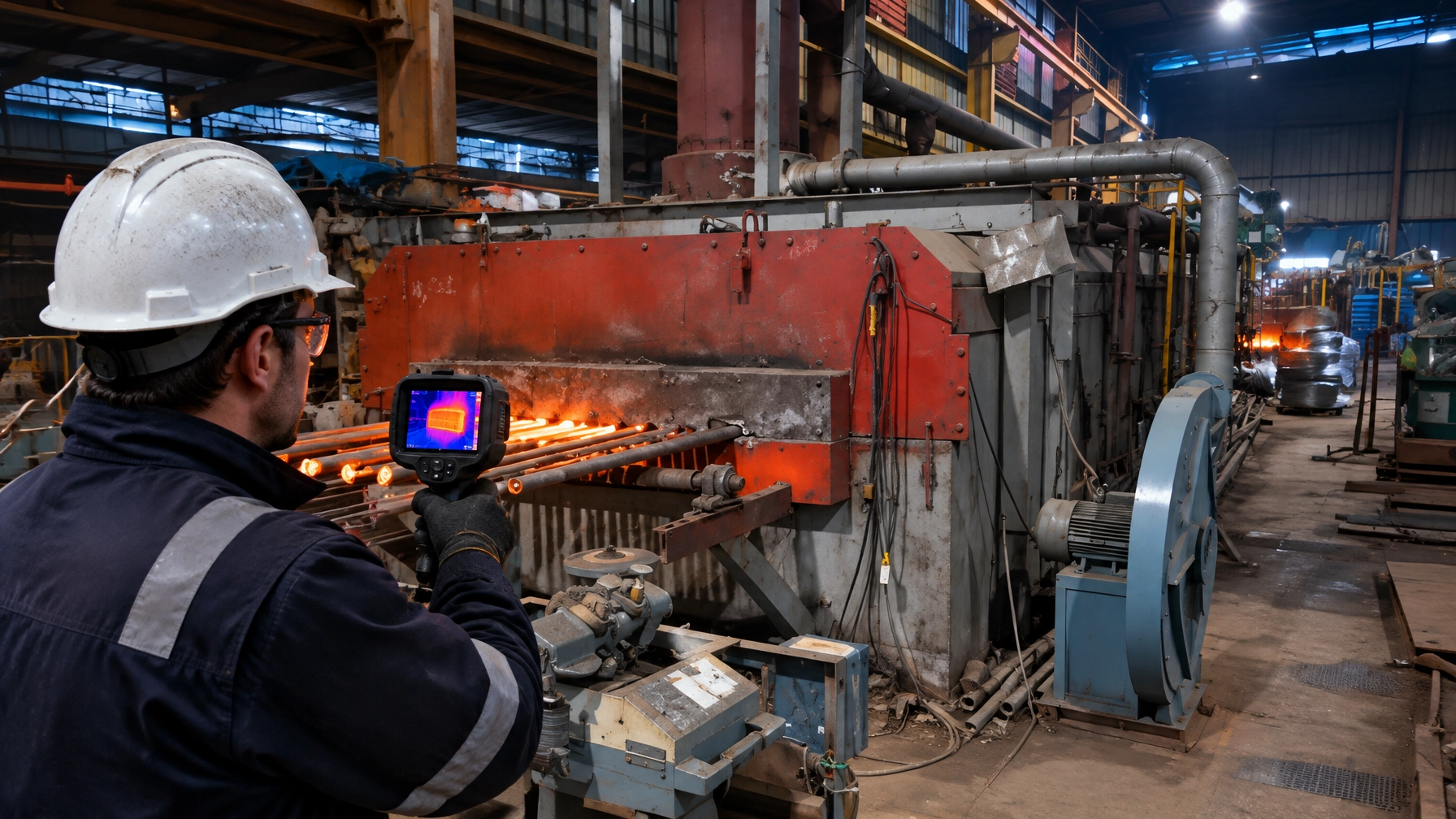
The furnace shell is the one diagnostic surface operators can inspect every day. Yet it is often treated as cladding rather than as an instrument: one that can reveal changing refractory and insulation performance before a visible failure forces a shutdown.
A disciplined infrared thermography program turns those observations into a ranked, trendable repair list. It also makes shell heat loss measurable: every degree above a suitable baseline represents energy leaving the process and, over time, additional stress on the steel shell. The objective is not to diagnose internal lining condition from one image. It is to detect change early, verify it under comparable conditions, and direct engineering effort where it can improve safety, uptime and profitability.
What the shell tells you: the cost of heat you can touch
The US Department of Energy’s Winter 2009 Energy Matters article, by DOE energy expert Dr. Arvind Thekdi, reports that heating systems typically lose 2–5% of total heat input through insulated surfaces. With proper material selection, design, installation and maintenance, those losses can be reduced by 10–25%. These are broad published benchmarks, not guaranteed savings for any specific furnace.
The DOE’s worked example shows why the fuel cost is greater than the raw shell-loss heat:
- A natural-gas furnace has 500 ft² of external surface at 200°F, with ambient temperature at 75°F.
- Estimated surface loss is about 275 Btu/ft²·hr, or 137,500 Btu/hr.
- With flue gas at 1,400°F and 5% O₂, available heat is approximately 55%. Replacing one unit of shell loss therefore requires about 1 ÷ 0.55 = 1.82 units of burner fuel.
- In the published example, reducing shell temperature to 150°F cuts surface heat loss by approximately 35%, to about 90,000 Btu/hr. At 8,000 hours per year and $10/MMBtu, the example reports savings of more than $7,200 per year.
That dollar value is the DOE example’s result, not a forecast for every plant. Local fuel prices, operating hours, furnace conditions and heat balance determine actual economics. Shell heat-loss assessment complements, rather than duplicates, the door and infiltration issues covered elsewhere in this series.
The physical calculation matters. External loss is a combination of convection and radiation, and depends on surface temperature, ambient conditions, orientation, wind and emissivity. Shiny and oxidised steel can produce very different infrared readings. For fuel-fired equipment, correct the measured heat loss for available heat before estimating the replacement fuel requirement.
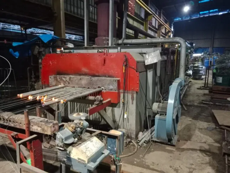
In a steel rolling mill, repeatable reheating-furnace shell surveys can help identify changing conditions around skid and riding zones. The same monitoring approach applies to broader thermal processing equipment, from a melting furnace for steel with EAF or induction shell panels to an aluminum melting furnace with shell hot spots near melt zones and launder areas.
Building the thermography program that actually trends
Thermography is only as useful as the measurement discipline behind it. The goal is a comparable record of shell condition, not simply a collection of colourful images.
- Verify calibration at least every 12 months for each temperature range, filter and lens in use, following the inspection guidance in FLIR/ITC Technical Publication 52.
- Use thermographers certified at minimum Level I under ASNT SNT-TC-1A, within the industry framework aligned with ISO 18436-7. Level I collects data; Level II interprets it; Level III manages the program.
- Establish emissivity against a contact reference or thermocouple. Measure reflected apparent temperature from the opposing wall and record the reference method for each zone.
- Repeat the same route, positions and viewing angles at each survey. Use fixed access points, camera jigs or field-of-view templates where practical.
The classic misreading trap is viewing angle. Effective emissivity falls as the observation angle increases. The hot opposing wall can then reflect into the camera reading, creating an apparent hot spot on the shell that is not a true local lining defect. Verify suspicious readings from a more suitable angle and against a reference rather than immediately issuing a repair order.
Scan both during start-up and at full rate. Cracks, gaps and voids may show as hot during heat-up, then close or become less visible as the refractory expands. A hot spot that persists at operating temperature is more likely to warrant investigation. Record operating state, load, ambient temperature, wind, camera setup and emissivity with each survey. Outdoor wind and changing ambient conditions can distort readings; monsoon humidity can also make survey conditions less consistent. Thermography on complex multilayer linings is fundamentally a relative-assessment tool, best used for trending, not as an absolute measurement of internal condition.

Hot-spot triage: from image to work order
There is no universal “how hot is too hot” threshold. The site’s maximum allowable shell temperature, personnel safety requirements and business interruption cost must govern. The following Delta-T bands are a conservative rule of thumb attributed to one consultant, not a universal engineering limit. Delta-T means the difference between the local shell reading and the selected ambient reference.
- 1–35°C above reference: minor; check periodically.
- 35–70°C: problem; monitor periodically and compare with history.
- 70–100°C: concern; increase monitoring frequency and assess corrective options.
- More than 100°C: high concern; monitor and take corrective measures as site conditions require.
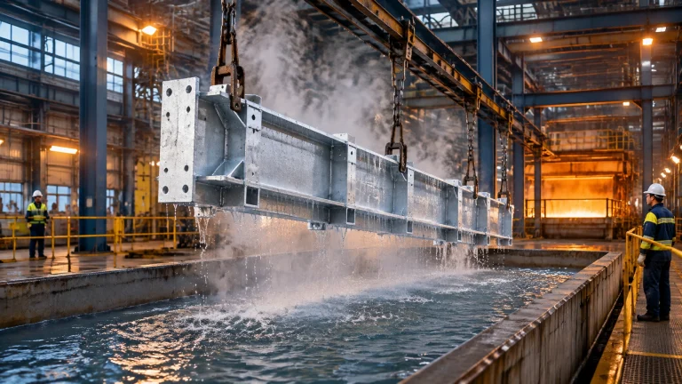
Prioritise location, trend and consequence, not temperature alone. Areas vulnerable to deterioration include welded joint sections, corners, seams, man-ways, roofs, sight ports and burner areas, plus the top 180° of refractory-lined piping. For a metal recycling furnace, inspect known slag-attack zones in the lining. In the wire and cable industry, include bell and continuous-annealing furnace door zones in repeatable routes. A hot dip galvanizing plant can include the kettle surround and bath-side shell in its monitoring plan; see Continental Furnaces’ plant gallery.
When operation must continue, external cooling such as steam lances or spargers, and injectable online refractory repair, may serve as interim controls if engineering review confirms they are appropriate. Some hot spots still require shutdown. Refractory repair usually means a full plant shutdown because there is no standby furnace; that is precisely why trending beats reacting.
| Approach | What it finds | Capital intensity | Best fit | Principal limitation |
|---|---|---|---|---|
| Route-based external shell thermography | Relative shell-temperature patterns and change over time | Low–medium | Routine surveys across accessible furnace surfaces | Requires disciplined emissivity, conditions and repeatable angles |
| In-furnace viewing through ports with flame-suppression filtered cameras | Internal lining surface patterns through available ports | Medium–high | Targeted inspection where safe access and suitable ports exist | Visibility, flame interference and access limit coverage |
| Fixed sheathed thermocouples on critical shell zones | Continuous temperature trend at selected points | Low–medium | Critical zones needing alarms or continuous oversight | Point measurements can miss defects between sensors |
| Pre-turnaround full refractory survey | Broad inspection and repair scope before planned shutdown | Medium | Shutdown planning and lining work-pack development | Episodic; does not replace operating-condition trending |
| Insulation upgrade retrofit, such as ceramic-fibre lining over suspect zones | Improved thermal resistance at confirmed hot zones | Medium–high | Engineered repairs with quantified heat-loss opportunity | Requires design validation and usually planned shutdown access |
Insulation upgrade economics: the hot-zone payback math
Insulation cost generally rises roughly linearly with thickness, while the savings from each additional increment fall. That creates an optimum thickness: a design point where material and installation cost, expected energy savings, temperature limits and operating life balance to the shortest practical payback. Multilayer construction, hot-face refractory with insulating layers behind it, is often the economic optimum because each layer performs a different job.
Material selection must account for:
- Thermal performance: temperature limit, conductivity, heat capacity and thermal-shock resistance.
- Physical properties: density, strength and abrasion resistance.
- Chemical compatibility: process atmosphere, slag or vapour exposure and operating conditions.
- Economics: installed cost, access, expected service life, shutdown scope and fuel savings.
At 100°F, DOE’s cited material data gives ceramic-fibre blanket at 4 pcf a conductivity of about 0.009 Btu/hr-ft-°F, compared with about 0.14 for low-density castable and 0.43 for high-density castable. Conductivity rises with both density and temperature. Lower-density insulating materials also store less heat, a relevant design consideration for cyclic furnaces.
For heat treatment furnaces processing cyclic batch loads, thermal mass affects both stored energy and heat-up or cool-down behaviour. Carpenter and Kissock describe lumped-capacitance and finite-difference methods for assessing heat storage in refractory, conveyors and racking. Their paper reports one case study with about a 78% reduction in surface heat loss after insulating hot surfaces: a single published case, not a typical or promised result. See Continental Furnaces’ heat treatment furnace solutions.
For screening and design, DOE/NAIMA’s 3E Plus and DOE’s Process Heating Assessment and Survey Tool (PHAST) are useful references; note that these are legacy tools. DOE’s current software suite is MEASUR, including a Wall Heat Loss Calculator. Use the tools to structure analysis, then validate assumptions against site conditions and material suppliers’ data.

A phased roadmap for shell heat-loss management
- Phase 1: Baseline Thermal Survey. Use a calibrated camera, establish emissivity by zone, and complete repeatable full-rate and start-up passes. Record operating and ambient conditions.
- Phase 2: Triage & Interim Control. Rank findings using site limits, the Delta-T guideline and trend history. Apply external cooling or online injectable repair only where justified by engineering and safety review.
- Phase 3: Insulation Engineering. Design the multilayer lining, review thermal mass for cyclic furnaces and evaluate optimum thickness using 3E Plus or PHAST as applicable, alongside current MEASUR tools.
- Phase 4: Execution at the Next Planned Shutdown. Inspect anchors, install modules and repair the identified zones. Check door and curtain sealing while access is available; DOE Tip Sheet #7 notes that flexible ceramic strips, chains or textile curtains at continuous-furnace openings generally reduce heat loss by half.
- Phase 5: Verification & Trending. Repeat the survey under comparable conditions, compare fuel or energy intensity such as kWh/kg or Sm³/t against the baseline, and maintain a quarterly route.
Spares that protect the repair window
Planned availability of furnace spare parts helps keep an identified defect from becoming a prolonged outage. Consider maintaining appropriate stock of:
- Anchor systems and anchoring hardware.
- Ceramic-fibre modules and blanket.
- Sight-port glass and gaskets.
- Sheathed thermocouples for critical shell monitoring.
- Burner tiles and door or curtain materials.
The correct stock depends on furnace design, service conditions and lead times. Aligning spares with a repair plan supports faster execution and minimal downtime.
Make the shell part of the operating strategy
An enduring partnership connects condition data to engineering, planned shutdowns and lifecycle value. Continental Furnaces brings 35+ years of expertise, ISO-certified quality, customized solutions for different industries and prompt service to support that work. As an experienced industrial furnace manufacturer, we help customers evaluate their requirements across industrial furnace systems, from condition monitoring to refractory and insulation upgrades.
Request a consultation or quotation to develop a shell-monitoring and insulation plan tailored to your equipment, operating profile and shutdown strategy. Take the next step toward sustained competitive advantage, with the right furnace spare parts and support in place.
References
- US Department of Energy, Energy Matters, Winter 2009, “Maximize System Energy Efficiency with Proper Insulation” (Dr. Arvind Thekdi). DOE PDF
- US DOE ITP, Energy Tips – Process Heating Tip Sheet #7: Reduce Radiation Losses from Heating Equipment (2006).
- Frisk, P., “Infrared Scanning of Furnaces,” FLIR/ITC Technical Publication 52. Publication
- James, S., “The Fundamentals of Refractory Inspection with Infrared Thermography,” IRINFO (2006).
- Carpenter, K. & Kissock, J.K., “Energy Efficient Process Heating: Insulation and Thermal Mass,” SAE 2006 World Congress / University of Dayton.
- “NDT Techniques for Furnace Refractory Lining Assessment” (2024), doi:10.58286/30021.