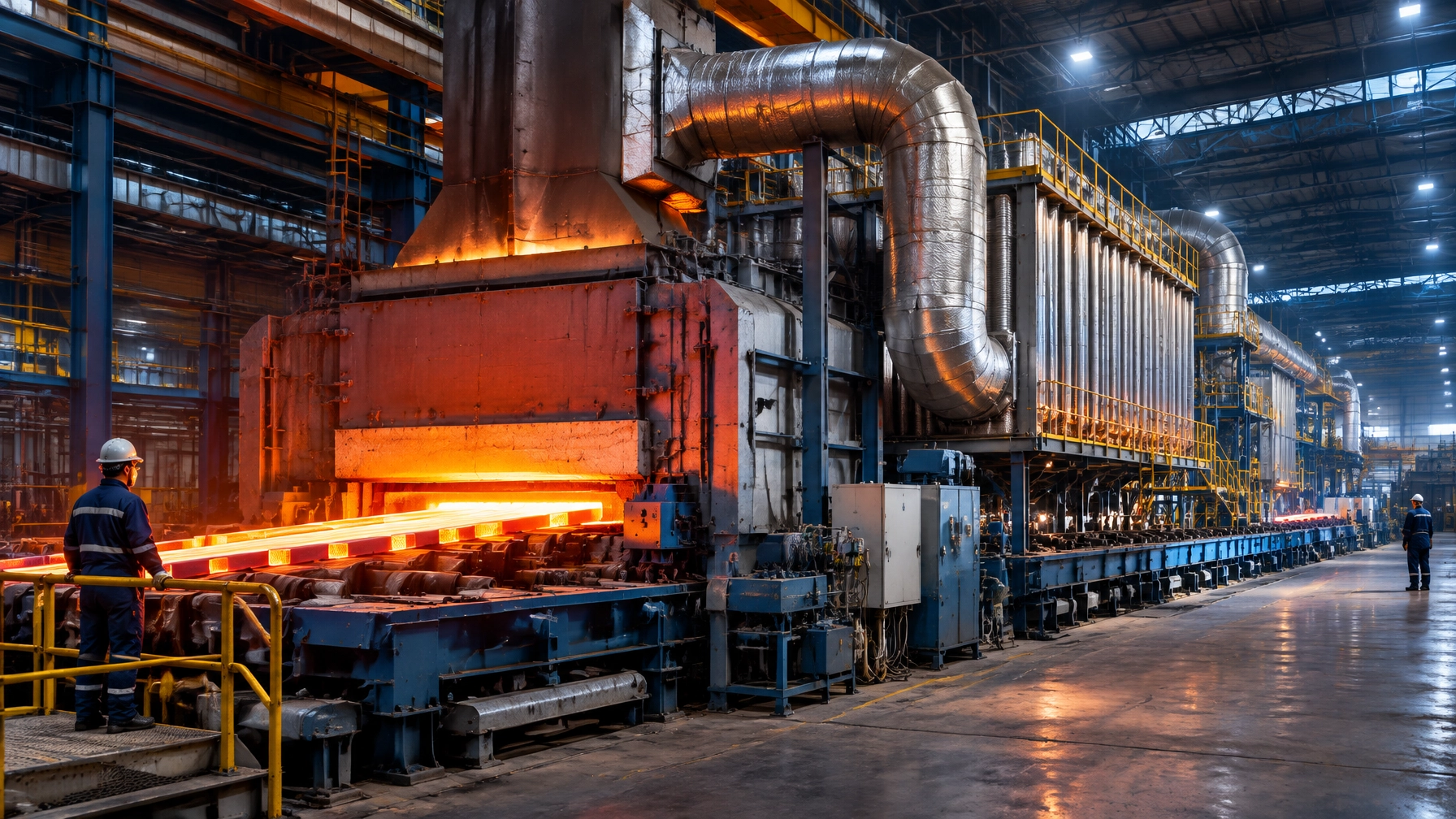
The largest recoverable energy stream is leaving through the stack
For many fuel-fired industrial furnace systems, the flue gas is the single largest recoverable energy stream. Depending on furnace design, operating temperature, excess air, insulation, and production loading, 20–30% of furnace input energy can leave through the exhaust before contributing useful heat to the product.
Typical exhaust conditions include:
- 250–450°C from lower-temperature heat treatment and galvanizing sections.
- 450–800°C from many continuous reheating, annealing, and pickling-related heating systems.
- 800–1,200°C or more from melting furnace and high-duty combustion zones.
- Higher local temperatures at furnace exits before dilution, leakage, or heat exchange.
In practical terms, a steel rolling mill may be purchasing fuel to heat combustion air, while simultaneously discharging a hot gas stream capable of preheating that same air. The margin opportunity is direct: recover exhaust heat, reduce fuel demand, stabilize furnace temperature, and lower emissions per tonne of output.
The U.S. Department of Energy’s industrial waste-heat research identifies exhaust recovery, combustion-air preheating, and process integration as established pathways for reducing industrial energy intensity. For plant managers, the priority is not simply installing a heat exchanger. It is designing an integrated energy system that protects throughput, metallurgy, safety, and lifecycle profitability.
Where waste heat recovery creates value
1. Recuperators and preheated combustion air
A metallic or ceramic recuperator transfers heat from exhaust gas to incoming combustion air. The result is a hotter, denser, more stable air stream entering the burner.
Depending on the duty and operating profile, a properly engineered recuperator can deliver:
- 10–15% fuel reduction in many furnace applications.
- Combustion-air preheat commonly ranging from 250–650°C.
- Typical simple payback of 2–4 years.
- Lower stack temperatures while maintaining required furnace-zone temperatures.
- Improved flame stability and reduced burner demand.
Metallic recuperators are compact and suitable for moderate exhaust temperatures. Ceramic recuperators withstand higher temperatures and aggressive operating conditions, although material selection must account for thermal shock, dust loading, corrosion, and maintenance access.
In an existing steel rolling mill, upgrading the burner train, air piping, control valves, and recuperator as one engineered package is more effective than replacing a single component in isolation.

2. Regenerative burners
Regenerative burners use paired ceramic storage beds. One bed absorbs heat from outgoing exhaust while the other releases stored heat into incoming combustion air. The flow reverses periodically.
For high-utilization continuous furnaces, regenerative systems can recover approximately 40–50% of available flue-gas heat and reduce fuel consumption by 10–25%, depending on furnace condition and baseline performance. Payback is frequently within 2–4 years where production hours are high.
They are particularly relevant to:
- Walking-beam and roller-hearth reheat furnaces.
- Continuous heat treatment furnaces for bars, rods, and strip.
- High-throughput melting furnace for steel operations.
- Large aluminum melting furnace installations.
- Furnace systems with consistently high exhaust flow and temperature.
Regenerative burners require disciplined sequencing, pressure control, ceramic-bed inspection, and suitable filtration. They are a process upgrade: not a plug-in accessory.
3. Steam, hot-water, thermal-oil, and ORC recovery
When combustion-air preheating does not absorb all available heat, the next step is plant-level integration.
Potential users of recovered heat include:
- Boiler-feedwater or hot-water systems.
- Degreasing, cleaning, or process-wash sections.
- Thermal-oil circuits.
- Building and process heating.
- Steam generation through a waste-heat boiler.
- Organic Rankine Cycle systems for electricity generation from suitable medium-temperature streams.
ORC and thermal-oil systems become attractive when exhaust flow is continuous, predictable, and large enough to justify additional balance-of-plant equipment. A small batch furnace may not support an economical power-generation project, while a large melting shop or continuous rolling line may support a compelling business case.
Batch and continuous furnaces require different strategies
A batch furnace has a variable thermal profile. The exhaust stream rises and falls with charging, heating, soaking, door openings, and cooling. Recovery systems therefore require:
- Thermal buffering or bypass arrangements.
- Careful control during charging and door opening.
- Protection against condensation and corrosive gases.
- Heat storage or hot-water applications that can accept intermittent supply.
A continuous furnace produces a more stable exhaust stream. This makes it better suited to:
- Recuperative burners.
- Regenerative burners.
- Continuous combustion-air preheating.
- Preheat zones for billets, bars, strip, or wire.
- Waste-heat boilers and thermal-oil systems.
- Real-time heat-balance optimization.
The correct configuration depends on exhaust temperature, flow rate, contaminants, operating hours, fuel price, product mix, and available space.
Traditional exhaust versus modern recovery configurations
The following figures are indicative engineering ranges, not guaranteed results. Actual performance requires a plant-specific thermal audit and heat-balance model.
| Metric | Traditional non-recovery exhaust | Metallic/ceramic recuperator | Regenerative burner system | Steam, thermal-oil, or ORC recovery |
|---|---|---|---|---|
| Fuel consumption | 100% baseline | 85–92% of baseline | 75–90% of baseline | 75–90% after integrated recovery |
| Combustion-air preheat | 20–40°C above ambient | 250–650°C | 600–1,000°C potential | Application-dependent |
| Typical ROI period | No recovery benefit | 2–4 years | 2–4 years | 2–5 years |
| Operating labour | Manual burner and stack checks | Similar routine labour; added inspection | Higher control-system and ceramic-bed checks | Additional utility-system monitoring |
| Emissions impact | Highest fuel-related emissions | Reduced CO₂ per tonne | Strong reduction where utilization is high | Reduced fuel or purchased electricity |
| Best application | Low-capital legacy operation | Retrofit and medium/high-duty furnaces | Continuous high-temperature duty | Large, stable waste-heat streams |
Plant-wide energy management turns recovery into sustained margin
A heat exchanger delivers value only when it remains clean, correctly controlled, and connected to a measurable production result. This is why waste heat recovery should be integrated with an energy management system aligned with ISO 50001.
Core energy performance indicators should include:
- GJ per tonne of heated, melted, galvanized, or treated product.
- Fuel consumption per tonne of billet, bar, strip, wire, or alloy.
- Exhaust temperature and oxygen concentration.
- Combustion-air temperature and flow.
- Recuperator differential pressure.
- Burner turndown and firing rate.
- Furnace-zone temperature uniformity.
- Recovered heat delivered to secondary users.
- CO₂ emissions per tonne of saleable output.
An Industry 4.0 dashboard should connect flow meters, thermocouples, oxygen analysers, pressure sensors, burner management systems, and production data. Operators should see whether a rising stack temperature is caused by excess air, fouling, air leakage, poor loading, or a failing recuperator.

A practical four-phase implementation roadmap
Phase 1: Assessment and Thermal Audit
Measure before specifying equipment.
- Record stack temperatures at multiple production rates.
- Measure exhaust flow, oxygen, carbon monoxide, and pressure.
- Map fuel consumption against tonnes produced.
- Inspect insulation, doors, seals, burners, ducts, and fans.
- Identify heat users near the furnace.
- Separate batch, idle, charging, and full-load conditions.
This phase establishes the baseline and identifies whether the largest opportunity is combustion-air preheating, load preheating, hot-water recovery, or a broader plant integration project.
Phase 2: Specification and Heat-Balance Modelling
Build a heat balance around the actual operating envelope.
The model should calculate:
- Recoverable heat at minimum and maximum throughput.
- Expected combustion-air temperature.
- Pressure drop and fan capacity.
- Corrosion, dust, and fouling risks.
- Bypass requirements for start-up and abnormal conditions.
- Fuel savings, emissions reduction, and payback.
- Effects on product quality and furnace atmosphere.
For a steel rolling mill, this may involve billet or bar reheating. For a metal recycling furnace, the model must account for scrap variability, charge moisture, dust, and intermittent tapping. A hot dip galvanizing plant may require tighter integration between strip heating, exhaust treatment, and process-air demand.
Phase 3: Retrofit with Minimal Downtime
Retrofit planning must protect production commitments.
A controlled execution plan includes:
- Pre-fabricated ducting and skids.
- Burner and recuperator components prepared before shutdown.
- Isolation, bypass, and emergency operating arrangements.
- Off-shift installation where practical.
- Commissioning first at low load, then across the production range.
- Operator training and documented acceptance testing.
Continental Furnaces’ role as an industrial furnace manufacturer extends from equipment selection to integration, commissioning, and performance verification across thermal processing equipment.
Phase 4: Monitoring, Verification, and Continuous Optimisation
The first month after commissioning is decisive. Compare measured results against the model and baseline.
Review:
- Fuel saved per tonne.
- Stable furnace-zone temperatures.
- Product quality and metallurgical results.
- Stack temperature and oxygen trends.
- Heat-exchanger fouling.
- Fan power and pressure drop.
- Maintenance requirements.
- Actual financial payback.
Corrective actions may include burner tuning, oxygen-trim control, revised loading practices, insulation repair, or software alarms.
Where furnace spare parts fit into the lifecycle plan
Energy performance deteriorates when critical components age. Leaking doors, damaged refractory, blocked recuperator passages, worn burner nozzles, degraded seals, and inaccurate sensors can return a modern furnace to inefficient operation.
A lifecycle plan should therefore include:
- Burner nozzles, valves, regulators, and flame scanners.
- Recuperator tubes, ceramic modules, seals, and expansion joints.
- Thermocouples, oxygen probes, pressure transmitters, and control hardware.
- Refractory materials, door seals, rollers, and heating elements.
- Inspection intervals tied to operating hours and fuel consumption.
Continental Furnaces provides furnace spare parts and accessories to support reliability, rapid replacement, and minimal downtime. Upgraded burner and recuperator components should be treated as part of the furnace’s energy-performance lifecycle: not as isolated maintenance purchases.

Convert exhaust into competitive advantage
Waste heat recovery is no longer a peripheral sustainability project. It is a direct route to lower fuel consumption, stronger yield, reduced emissions, and improved profitability across steel rolling, melting, recycling, galvanizing, pickling, heat treatment, and the wire and cable industry.
With more than 35 years of engineering experience, Continental Furnaces designs customized industrial furnace systems around each plant’s production profile, available utilities, compliance requirements, and long-term business objectives.
The next step is a plant-specific heat recovery study. Consult Continental Furnaces engineers to measure your exhaust losses, model the recovery opportunity, and build a phased investment plan for sustained competitive advantage. Request a consultation or quotation.