3 November 2026 | Engineering deep-dive for steel and thermal-processing decision-makers
The unseen heat sink: skids move the load and silently drain fuel
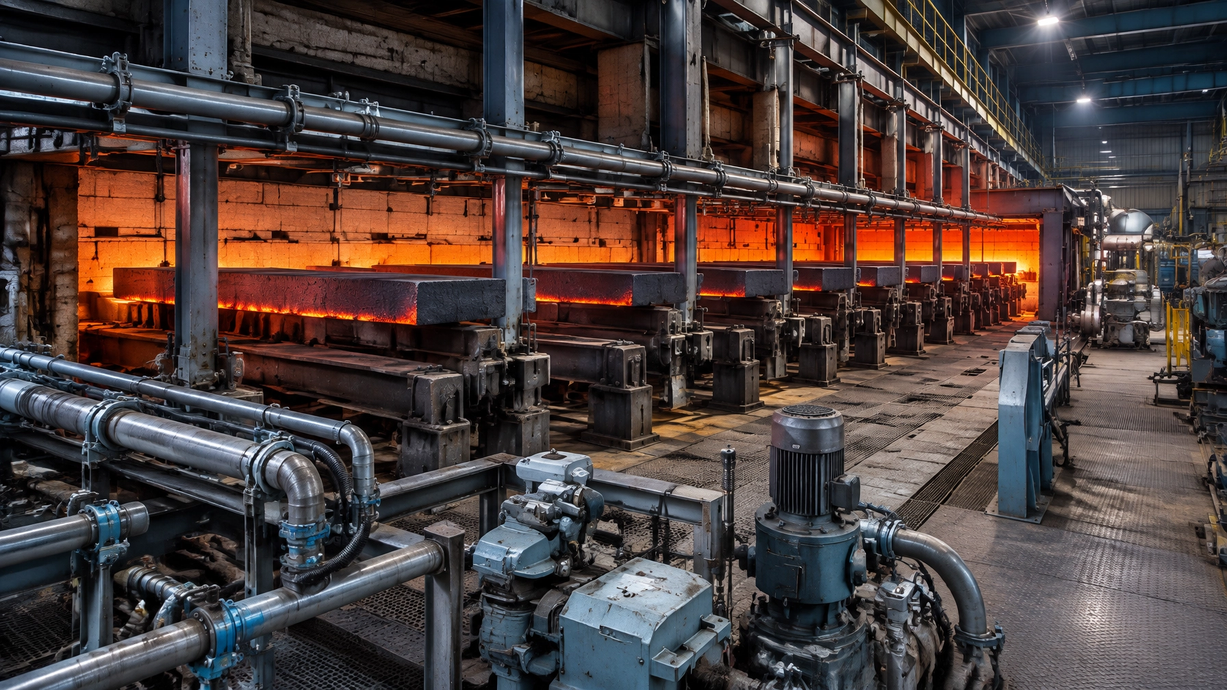
In a continuous reheat furnace, water-cooled skids and support posts perform an essential mechanical duty: they carry and move slabs through the furnace. At the same time, they draw heat away from the furnace and the load into the coolant. This loss is easy to miss in routine fuel reporting because the energy leaves through the cooling circuit rather than the flue.
For steel rolling mills, the issue links energy intensity, slab-temperature uniformity, maintenance and production availability. The same design principle applies to water-cooled rails or rollers in continuous heat treatment furnaces and, in other applications, to water-cooled components in an aluminum melting furnace, charging rails in a metal recycling furnace, or panels and yokes in a melting furnace for steel.
The engineering priority is not simply to add more insulation. It is to measure the cooling duty, design around scale and mechanical loading, and verify that thermal savings do not compromise support integrity or product quality.
Where the losses go
Water carries away heat absorbed by skid pipes, posts and related supports. Published studies commonly report skid-pipe cooling losses at 10–15% of energy provided for furnace heating; other published references place skid losses broadly in the 10–17% of fuel-input range. These are reference ranges, not universal plant benchmarks. Actual losses depend on furnace design, operating conditions, coolant flow, insulation condition and exposed surface area.[1][2][3]
Geometry matters. A walking-beam furnace typically has about 1.5 times the water-cooled surface area of a pusher-type furnace, reflecting its additional walking beams and posts. More cooled area can mean more potential heat transfer into the coolant. But the achievable reduction also depends on which surfaces can physically be insulated: rider arrangement, joints, supports and scale-exposed zones constrain the available area.
The loss persists because the circuit must remove enough heat to protect the equipment. It can remain largely invisible until coolant flow and temperature rise are measured alongside production and fuel data. In the overall heat balance, skid loss is one term among several; changes in it may also affect the furnace’s total fuel requirement. Flue-gas losses are relevant here only as part of that wider balance, not as a substitute for measuring the coolant duty.

Quantifying the skid you already have
The practical starting point is the heat absorbed by the cooling water:
Heat-loss rate = ṁ × cp × ΔT
Where ṁ is coolant mass flow rate, cp is its specific heat capacity, and ΔT is the temperature rise between circuit inlet and outlet. Record flow and paired temperatures over representative operating periods, then integrate the rate to estimate energy loss.
For a useful comparison:
- Measure each circuit separately where possible; circuit-level readings reveal which beams, posts or zones dominate.
- Compare readings at similar throughput, product mix, furnace conditions and coolant-flow conditions.
- Use dedicated test circuits, where available, for an A/B comparison between an insulated trial section and a comparable reference circuit.
- Track both the circuit’s heat duty and plant fuel intensity. A reduction in skid-water loss is not automatically the same percentage reduction in total furnace fuel use.
Published case results show the potential, and the limits of generalizing from a single installation. At ArcelorMittal Bremen, walking-beam furnaces WBF1 and WBF2 were rated at 420 t/h each, with a furnace length of 38.0 m and width of 15.8 m, serving a hot rolling mill with capacity up to 4.8 Mt/a. At WBF1, reported mean skid-system heat loss fell from approximately 1,260 GJ/day with RCF modules to 810 GJ/day with a new shell system: a reduction of 450 GJ/day, or about 35%.[1]
These figures describe one published furnace case, not a guaranteed outcome for another plant.
Insulation engineering: materials and geometry
At Bremen, earlier refractory ceramic fibre (RCF) modules had a 1,400°C rating and a 1,250°C continuous-use temperature. In service, scale crushed and attacked the modules, their low mechanical strength contributed to detachment from the tubes, and shrinkage indicated partial overheating. Large-area repairs were needed nearly every six months.[1]
The replacement concept used prefabricated shells in a modular sandwich construction: a heat-resistant metal sheet for attachment, an embedded alkaline-earth-silicate (AES) wool blanket, and a castable hot face. The lightweight shell used FLB-11/150-I1, based on SLA-92 calcium hexaluminate microporous aggregate. Dense FB-25/160-P1 castable was retained on skid top surfaces exposed to the greatest scale attack, with lighter shells used on bottom sides.
At 1,000°C, the published thermal conductivity values were about 0.30 W/mK for lightweight castable and 1.70 W/mK for dense castable, roughly a 75–80% reduction. Bulk density was 1.1 versus 2.5 g/cm³. In test-furnace trials, replacing dense with lightweight shells reduced heat loss per square metre of pipe surface by more than 60%, with CFD calculations confirming the result.[1] Published references also report that effective skid insulation can reduce bare-pipe heat loss by 60–90%, depending on system and conditions.

| Approach | What it is | Indicative conductivity or loss reduction (published, with caveats) | Mechanical durability vs. scale | Relative cost / installation time | Best fit |
|---|---|---|---|---|---|
| Bare / uninsulated pipe baseline | Exposed water-cooled pipe or support | Baseline; no insulation reduction | No shell to fail; high heat extraction | Lowest initial cost; no installation work | Reference case or locations where insulation is impractical |
| RCF fibre modules | Fibre insulation modules fixed around pipes | No universal reduction figure; effectiveness can decline with ageing or damage | Bremen case reported crushing, scale attack and modules falling off | Repair-intensive in that case; repeated shutdown work | Assess carefully where impact, scale and temperature challenge the modules |
| Dense castable | Castable refractory shell | About 1.70 W/mK at 1,000°C in the cited material comparison | Higher strength; useful on scale-attacked top surfaces | On-site casting can require forms and curing | Exposed, high-wear areas and geometry requiring robust protection |
| Prefabricated lightweight sandwich shells | Metal attachment sheet, embedded AES wool and microporous lightweight castable | About 0.30 W/mK at 1,000°C; >60% lower heat loss/m² than dense shells in cited trials | Modular design; published case remained stable for over 2.5 years | Prefabrication typically cut installation time by about 75% versus on-site castable in the cited case | Suitable pipe and post sections where geometry, temperature and attachment design permit |
These comparisons reflect published results and material data, not universal service-life or cost guarantees. The Bremen industrial result remained stable for more than 2.5 years, with almost no insulation maintenance reported. Installation time was typically reduced by about 75% using prefabricated shells. In that German case, circa 2010–2012, the reported cost reduction was at least €900,000 per year per furnace, against approximately €750,000 investment for the complete skid-pipe system, including removal and installation; reported payback was under one year.[1] This historical case is not a present-day price or ROI forecast for India or any other location.
Rider design can limit achievable savings: a hot-rider system may leave less surface available for insulation than conventional riders. Geometry must therefore be evaluated alongside material performance.
Quality coupling: skid marks and uniformity
Water-cooled skids act as heat sinks beneath the load. At skid contact points, slabs or billets can develop characteristic skid marks, localized cold spots that may persist into downstream rolling if heating time and uniformity are insufficient.
Common mitigation measures include adequate soak-zone residence, carefully managed soak-zone temperature, skid-rider geometry and improved insulation. Insulation reduces heat transfer into the pipe, but it does not eliminate the contact and shielding effects created by the support geometry. A 2025 numerical study examined the effect of higher coolant temperature on reheating performance; any coolant-temperature strategy requires site-specific mechanical, pressure and safety review before implementation.[5]

Risks and engineering safeguards
- Scale impact: use wear-resistant top caps where scale accumulation and slab movement attack the hot face.
- Chemical attack: select materials for the actual scale and furnace atmosphere.
- Thermal cycling: detail joints and shell geometry to accommodate cycling without premature cracking.
- Attachment integrity: inspect metal sheets, anchors and restraints; a good insulation material cannot compensate for a failed attachment.
- Coolant flow: maintain circuit flow monitoring and investigate abnormal temperature-rise trends promptly.
- Added weight: check pipe and support loading before over-insulating; the shell assembly must remain within structural limits.
- RCF handling: where existing RCF is removed, apply appropriate handling, exposure controls and site procedures.
A five-phase retrofit roadmap
- Baseline coolant audit per circuit: record flow, inlet/outlet temperatures and operating context.
- Rank by area and loss rate: prioritize circuits with high heat duty, large exposed surface or recurring insulation damage.
- Pilot one circuit with A/B measurement: select a representative section and confirm the comparison method before installation.
- Measure and verify: compare coolant duty, fuel intensity and product temperature uniformity at matched operating conditions.
- Institutionalize planned maintenance: record shell condition, repairs, circuit performance and shell-life trends in the maintenance system.
Keep the support system serviceable
A dependable furnace spare parts strategy includes prefabricated insulating shells, attachment and anchor systems, rider pads, coolant hoses and valves, flow meters, and RTDs or thermocouples. Stocking critical items around the actual furnace design supports planned work and reduces the risk that a small component issue becomes extended downtime.
The same systems view matters beyond a steel rolling mill: water-cooled rails and rollers may be relevant in continuous heat treatment; charging-frame components in an aluminum melting furnace; water-cooled panels or yokes in a melting furnace for steel; hearth supports in a hot dip galvanizing plant; and charging rails or annealing-line internals in metal recycling and the wire and cable industry. The appropriate design depends on the application and operating conditions. An experienced industrial furnace manufacturer should assess the complete industrial furnace systems interface (thermal, mechanical, coolant and maintenance) not only the refractory layer.
Coolant return water can also be assessed as a possible low-grade heat source where a suitable demand exists. Treat that as a separate site-level evaluation after the skid loss has been quantified.
Continental Furnaces brings 35+ years of expertise, ISO-certified quality, customized thermal processing equipment solutions and super prompt service to support an enduring partnership across design, operation and maintenance. For a circuit audit, retrofit discussion or project proposal, request a consultation or quote and identify the next step toward sustained competitive advantage.
References
- ArcelorMittal Bremen / FBB Engineering / Almatis, “Energy saving in walking beam furnaces at ArcelorMittal (Bremen, Germany) by a new concept for skid pipe insulation.” Published paper
- Hoffelner et al., “Reduction of heat losses on the skid pipe system of a pusher type furnace at voestalpine Grobblech GmbH in Linz, Austria,” 55th International Colloquium on Refractories, Aachen, 2012. Published paper
- U.S. DOE Industrial Technologies Program, “Waste Heat Reduction and Recovery for Improving Furnace Efficiency.” Technical brief
- ORNL/DOE, “Process Heating Assessments Using DOE’s Manufacturing Energy Assessment Software for Utility Reduction (MEASUR) Tool Suite.” Assessment paper
- Yunus Ahmed et al., “Numerical investigation on the influence of the skid coolant temperature on the reheating furnace performance,” Thermal Science and Engineering Progress, 2025. Article DOI